


 1709 / 1906

SUPPLEMENTARY RESTRAINT SYSTEM (SRS)
18
SRS ECU FITMENT
For fitment follow reverse procedure of removal.
PRECAUTIONS
If the ECU is accidentally dropped on the con-
crete floor from the height of more than 1m then
that ECU should not be used on a vehicle.
ECU should be transported with proper packing
material.
Always store the ECU in dry place.
A person handling any restraints module assem-
bly shall have to wear ESD
(electro-static dis-
charge)
straps to reduce any risk of inadvertent
deployment.
NOTE:
After removal / fitment of components – SRS ECU,
Sensors, DAB, PAB, RPLL, connect service tool and
check for DTCs to ensure the system behavior as
expected.
II SENSORS
FRONT IMPACT SENSOR
(FIS)
These sensors are positioned well forward in the
crumple zone so that, it will react almost instantly to
the sudden deceleration that results from the front
impact. They send signal to the SRS ECU and help
in firing the restraints in the minimum possible time.
These sensors are equipped with
“Safe Mode”
func-
tion to ensure that the SRS fires only when there is a
physical crash event of significant severity.
MAKE: BOSCH
SUPPLY VOLTAGE RANGE: 5.25 V to 16.5
CAUTION
Do not attempt to check or replace any impact sen-
sor unless the vehicle battery is disconnected. This
renders the sensing system "powered OFF". Wait for
at least 10 minutes after the battery is disconnected
and then start the relevant work/repair.
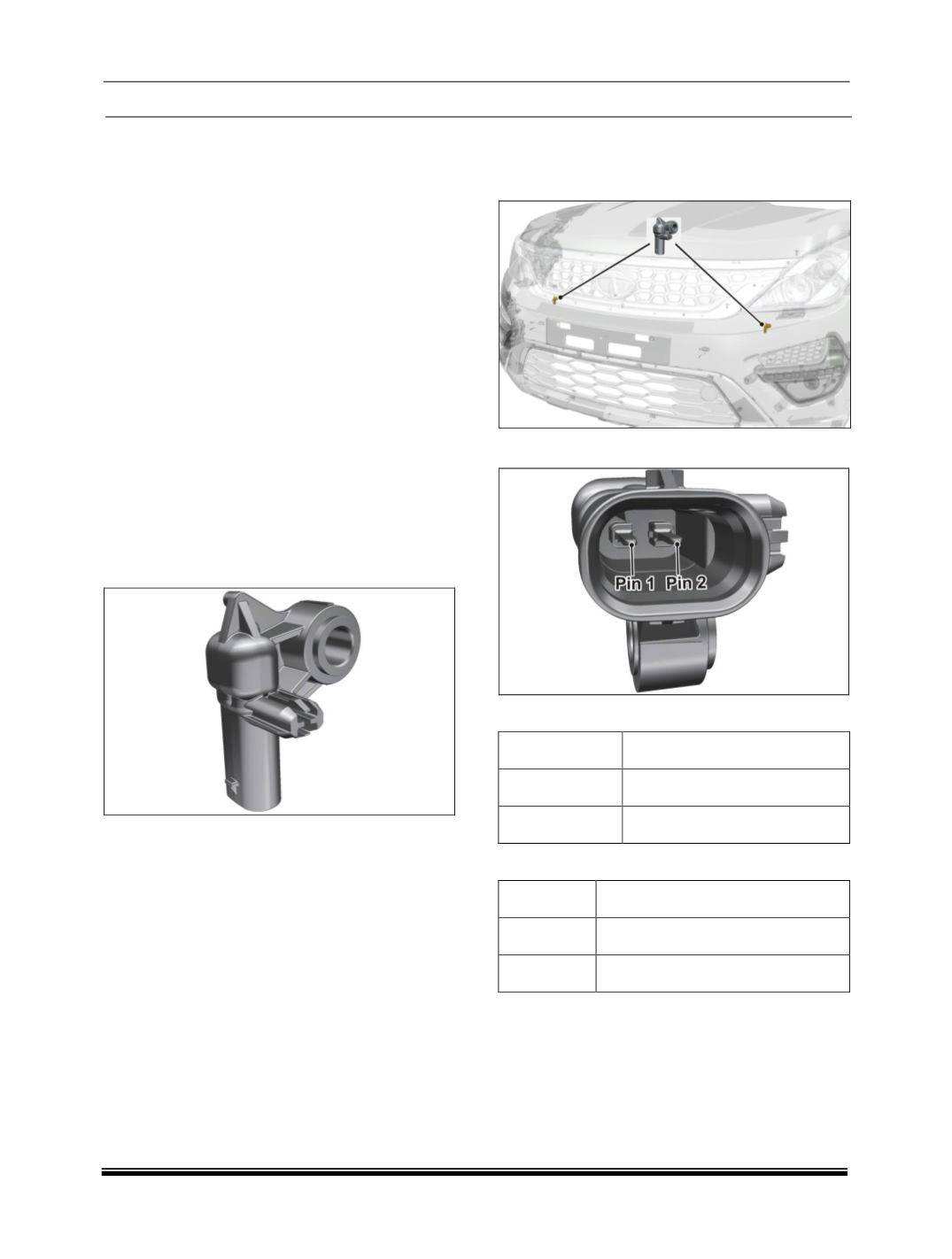
LOCATION
Front impact sensor is mounted on the first body
mount bracket.
CONNECTOR
PINOUTS
PIN NO.
PIN DESCRIPTION
1
Signal
2
Ground
SUPPLY VOLTAGE LEVEL
Minimum
5.25 V
Nominal
6.20 V
Maximum
16.5 V