


 1705 / 1906

SUPPLEMENTARY RESTRAINT SYSTEM (SRS)
14
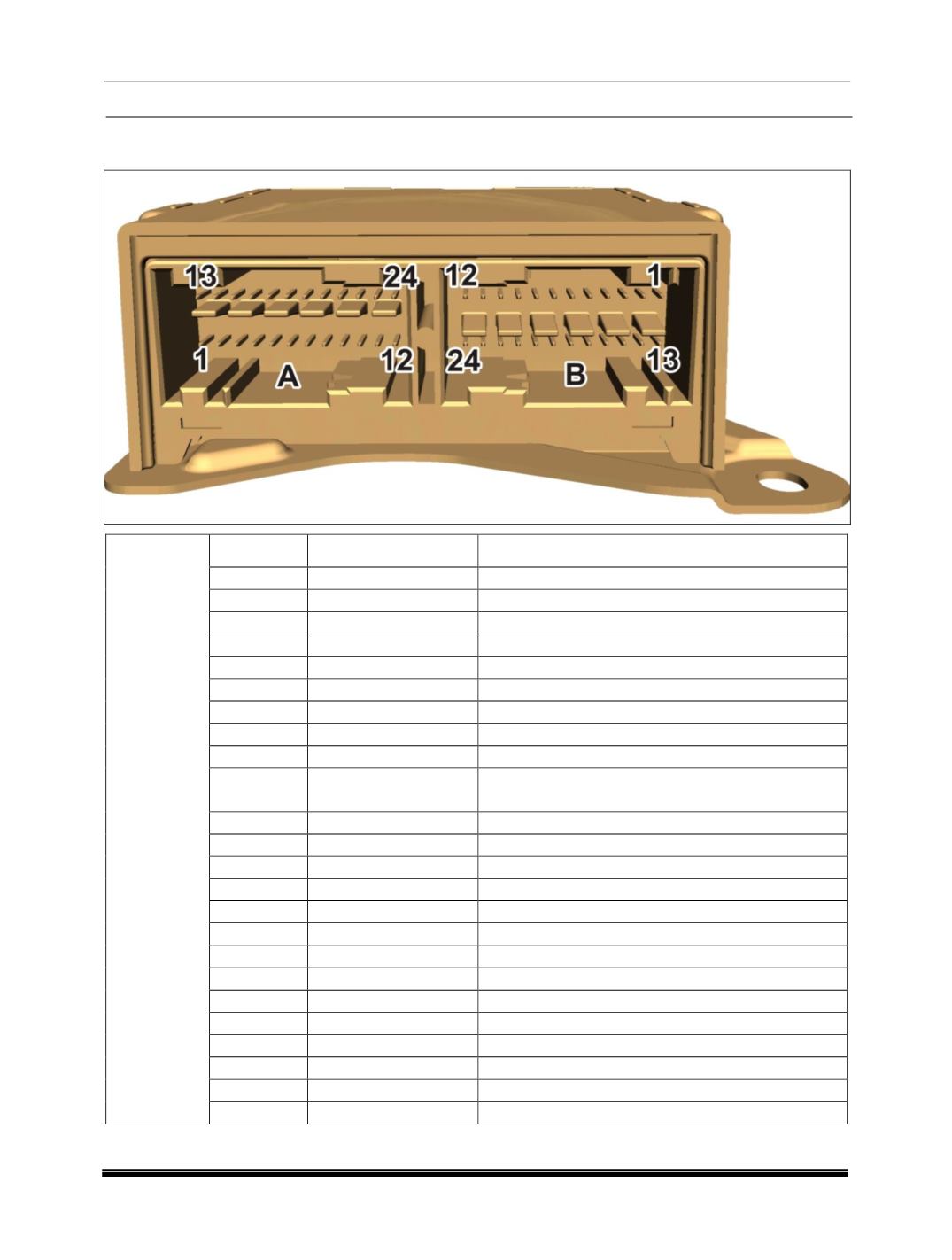
SRS ECU CONNCETOR
CHAMBER
A:
Pin No.
Pin Name
Description
1
CAN_H
CAN High
2
CAN_L
CAN Low
3
LSD
Low side driver
4
NA
Not Applicable
5
CRO
Crash Output
6
NA
Not Applicable
7
A_GND
Common Switch GND
8
BLRM
Rear Middle Buckle Switch
9
PADS
Passenger Airbag Deactivation Switch
10
BLFP+PPD
In Series Connection of Passenger Buckle Switch
and passenger detection mat.
11
NA
Not Applicable
12
V bat
Supply Voltage Battery
13
BLRD
Rear Buckle Switch Driver Side
14
BLRP
Rear Buckle Switch Passenger Side
15
ABFD-
Front Airbag Driver, Minus
16
ABFD+
Front Airbag Driver, Plus
17
ABFP+
Front Airbag Passenger, Plus
18
ABFP-
Front Airbag Passenger, Minus
19
BTFD-
Belt Tensioner Front Driver, Minus
20
BTFD+
Belt Tensioner Front Driver, Plus
21
BTFP+
Belt Tensioner Front Passenger, Plus
22
BTFP-
Belt Tensioner Front Passenger, Minus
23
GND
Power GND
24
PADI
Passenger Airbag Deactivation Indicator