


 1443 / 1906

ELECTRICAL
141
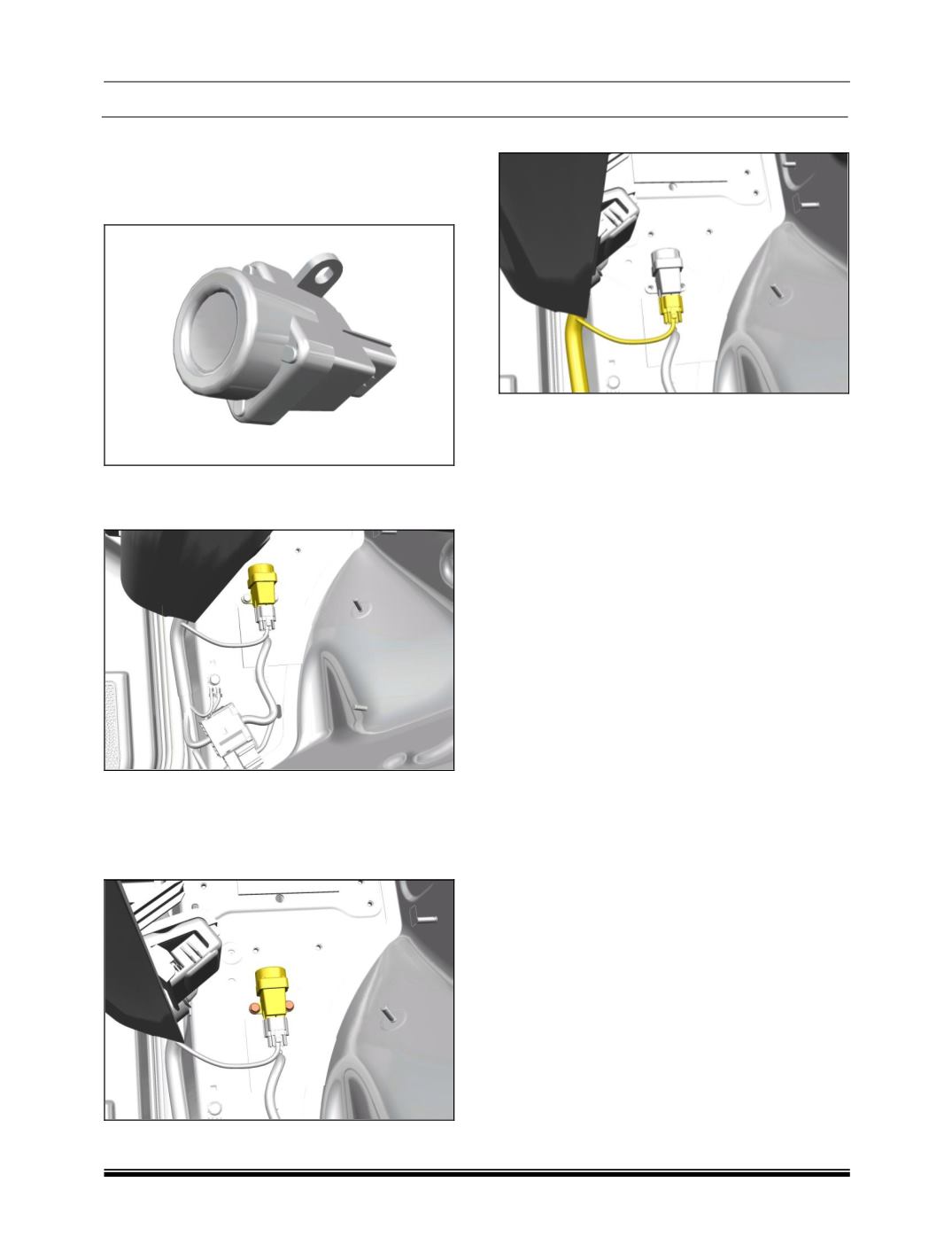
8.9.13 INERTIA SWITCH
FUNCTION:
Inertia switch gives input to BCM for unlocking
doors in event of impact.
LOCATION:
It is located on LH side ‘A’ pillar at inner lower.
REMOVAL:
1. Remove the lower A pillar trim. (
Refer body
section
)
2. Remove the two mounting screws.
3. Disconnect the electrical connection.
4. Take out the switch.
REFITMENT:
1. Fit the inertia switch by tightening its two
screws.
Tightening torque for screws – 0.6 Kgfm
2. Connect the electrical connection.
3. Fit the A pillar LH lower trim.