


 1291 / 1906

STEERING
33
C. DISMANTLING,
INSPECTION
AND
ASSEMBLY :
i. OUTER BALL JOINT
(OBJ) :
Dismantling:
1. Plug the pressure and return port, Clean/wash
the Steering gear thoroughly. Mount the
steering gear in the suitable fixture or vice.
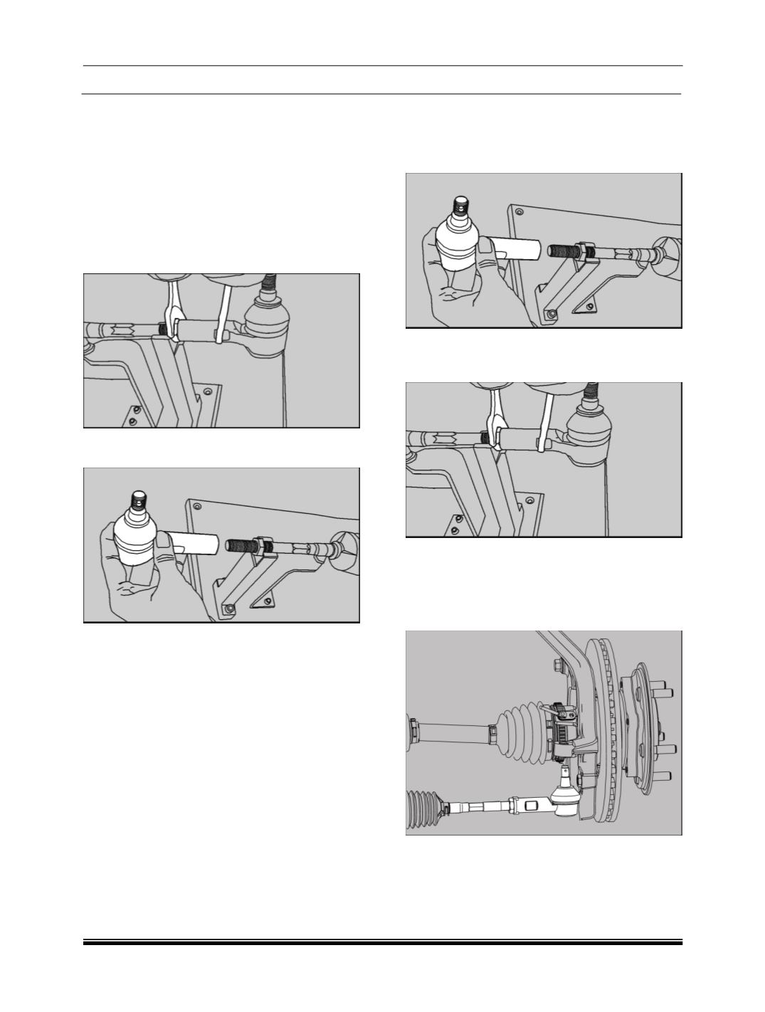
2. To remove the outer ball joint hold the inner
ball joint assembly with the spanner and
loosen the OBJ lock nut.
3. Unscrew the OBJ and remove the same from
IBJ.
NOTE:
Follow the same procedure for other end also.
INSPECTION:
The outer ball joint assembly must be replaced if
either of following conditions is detected:
Any binding in articulation of ball pin.
Any axial play between the ball and cup of the
outer joint assembly, more than 0.1mm, when
checked by slightly pulling/ pushing by hand.
Assembly:
1. Put the OBJ Lock Nut on the IBJ assembly.
2. Fix the OBJ into the IBJ to the half portion of
the IBJ.
3. Assemble the OBJ on both sides with equal
number of threads. Tighten the lock nut
against the OBJ to the specified torque.
OBJ ON-VEHICLE REMOVAL:
NOTE:
RAP need not be removed; to remove OBJ on
vehicle disconnect the OBJ at Steering
Knuckle.
Refer on bench OBJ removal process.