


 1330 / 1863

ELECTRICAL
28
Note:
The grooved ball bearing seal may be damaged if
the cap is not pierced in the center with a suitable
tool.
5. Fitted cover can only be removed by piercing
and prising out.
Note:
The grooved ball bearing seal may be damaged if
the cap is not pierced in the center with a suitable
tool.
6. Insert suitable assembly tool (2) in splines of
freewheel pulley (1).
7. Use the multi-point attachment (3) to stop the
rotor shaft and unfasten the freewheel pulley
with a box wrench.
8. Detach freewheel pulley.
2
.
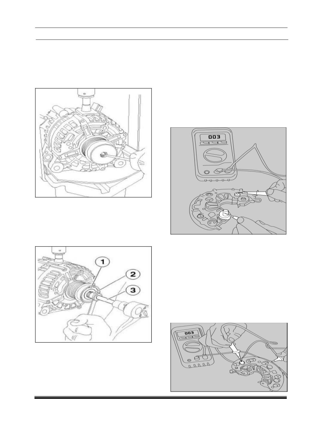
TESTING INSTRUCTIONS:
2.1. TESTING OF RECTIFIER.
2.1.1 Testing of Positive power diode:
Place the black probe of the multi-meter on the
terminal B+ and red probe on the each of the
points where the stator winding ends are soldered
on the rectifier
(Points M1, M2, M3, M4, M5, M6).
Reading should be between 0.300V and
0.900V.Reverse polarity i.e. red probe on B+ and
black probe successively on M1, M3…..No
current should flow in this case i.e there should be
‘0’ appreciable change in the multi-meter reading.
2.1.2 Testing of Negative power diode:
With red probe of the multi-meter on the lower
hear sink into which the negative power diodes
are pressed i.e. D- and black probe on the M1,
M2, M3……. the multi-meter reading should be
with in 0.300V and 0.900V. Interchanging the
probe
(black on D).
No current should flow. Even
if one diode found defective in the above tests,
the rectifier assembly has to be replaced.
NOTE:
There are no excitation diodes in E8 155A
alternator.