


 1081 / 1863

REAR AXLE
32
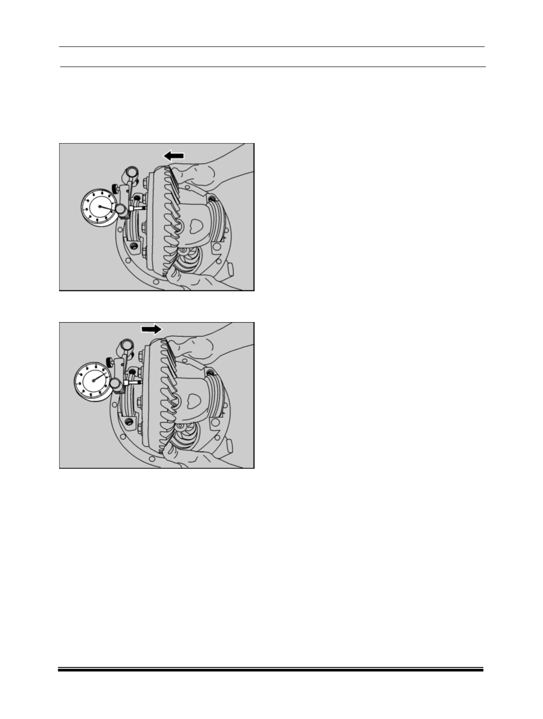
10.Place differential assembly into housing. Install
dial gauge and locate tip of indicator on the
surface of one of the ring gear screws. Force
differential case assembly away from pinion
gear. With force still applied set indicator at 0
(Zero)
.
11.Force differential case assembly and ring gear
to mesh with pinion gear.
12.Rock the ring gear to allow teeth to mesh.
Repeat to obtain a stable reading. Record in
given format as B.
13.Remove indicator and master differential
bearings.