


 887 / 1236

ELECTRICAL
109
ELECTRICAL
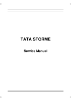
FITEMENT DEATILS
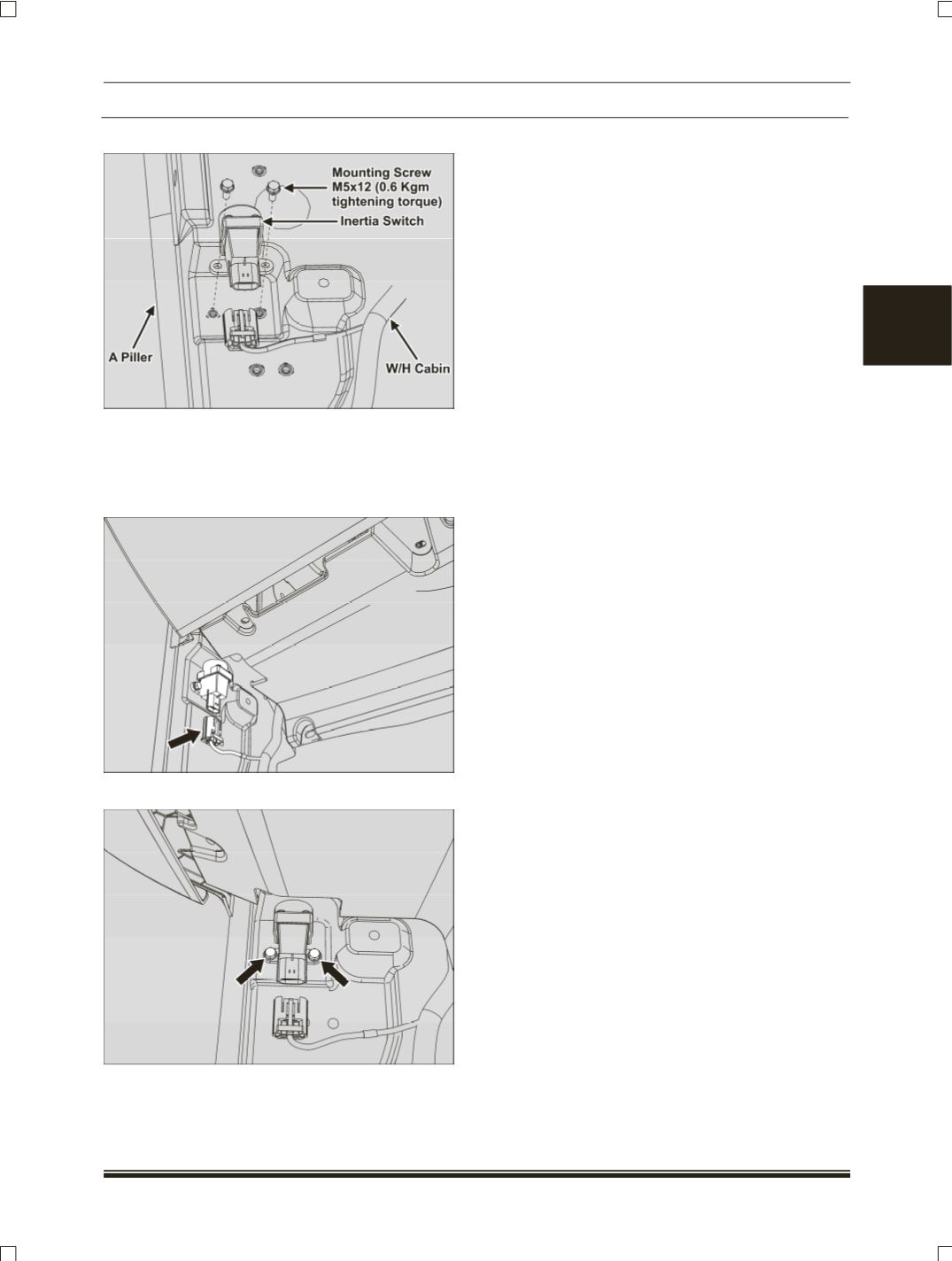
REMOVAL:
1. Remove the lower A pillar trim. (
Refer body
section
)
2. Disconnect the electrical connection.
3. Remove the two mounting screws.
4. Take out the switch.
REFITMENT:
1. Fit the inertia switch by tightening its two
screws.
Tightening torque for screws – 0.6 Kgm
2. Connect the electrical connection.
3. Fit the A pillar lower trim.