


 76 / 1526

47
4 DLT ENGINE
REMOVAL, INSTALLATION AND MACHINING OF
CYLINDER LINERS
In order to obtain optimumperformance of engine after
reconditioning with liner fitment, we are giving below
the machining procedure to be adopted in the field.
The disassembled cylinder block should be pressure
tested as per the procedure. The block with cracks
should be discarded.
REMOVAL
1. Keep cylinder block upside down on hydraulic press
such that bore from which liner is to be removed
lies clear in machine table slot.
2. Ensure that the block is resting squarely on
machine bed.
3. Press out liners individually using drift, 2654 5890
01 03 and a suitable distance piece between press
ramand the drift. Make sure that the distance piece
is also seating squarely between the drift and the
ram.
INSTALLATION OF LINERS IN CYLINDER BLOCK
Thoroughly clean bores of the cylinder block.
Thoroughly clean liners.
Place cylinder block on hydraulic press ensuring that
oil sump mating face is resting evenly and squarely
on the horizontal bed.
DO NOT SMEAR CYLINDER BORE OF BLOCK OR
LINER OUTSIDE SURFACE WITH OIL.
Place liner with proper orientation (matching minimum
/ maximum ovality axis) in the cylinder bore and make
it at right angles to cylinder block top surface in
longitudinal and crosswise directions using precision
tri-square.
Press liner using drift 2654 5890 01 02. Use a wooden
spacer about 100 mm thick between press ram and
drift. Pressing force should be within 4 to 6 tonnes.
Similarly, press all other liners.
Liners damaged during installation should be removed
and replace with new ones.
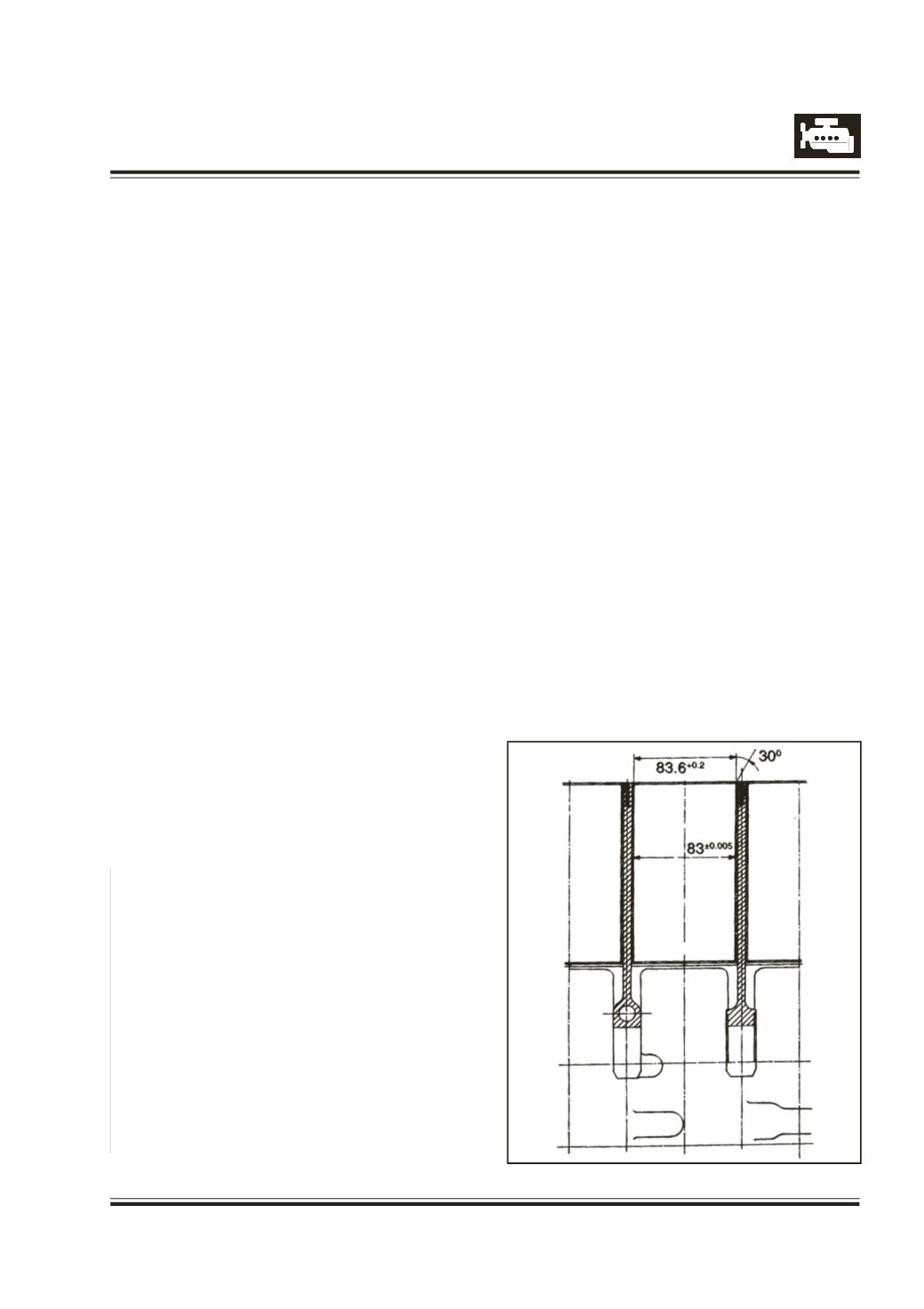
BORING OF CYLINDERS :
The cylinder liners are semifinished and it is necessary
tomachine the liners to 82.915 to 82.945mmdiameter.
NOTE :
It is very important that the axis of the bores are parallel
to each other and are at right angle to the axis of
crank shaft. Permissible shift in perpendicularity of
bore from crankshaft axis when checked at 200 mm
from crank shaft centre line is 0.040 mm. Therefore
we recommend the use of pillar type boring and honing
machines. If portable boring bar is used check and
clean mating surface of boring bar and cylinder block
and centralise the boring bar as accurately as possible
in the bore.
4 DL CYLINDER BLOCK HONING
1. PRE-MACHINING CONDITION
: Before Honing
a) After boring the barrel bore the stock (75 to 95
microns material) must be available for bore honing
option.
b) Centre line of these bores may be 0.04mm inclined
maximum in the longitudinal axis of block (crank
bore)
c) After boring taper and ovality should be within 15
um max. Surface finish 2.2 to 2.8 uRa or more.
2. CYLINDER BORE HONING :
2.1 Rough Honing :
With vertical honing machine operation to be carried
out with coolant "HONILO 480" honing oil or kerosene.
Flooded coolant to be used so that component bore
distortion should not take place.
Make the operation gently. Keep the 15 microns/
20microns stock for Base and Plateau honing. Maintain
the taper and ovality within 8 to 10 microns max. Most
preferable is within 5micronsmax. Surface finish value
at this generation must be 0.8 to 1.2 µm Ra.
Machining Data : RPM of Spindle - 100
Fig. 76