


 75 / 1526

46
4 DLT ENGINE
M
easure pre tension of main bearing shell with a feeler
gauge after loosening main bearing cap mounting bolt
on opposite side of bearing shell lug.
(This is to be done on a flat surface plate as it cannot
be measured on engine cylinder block because the
main bearing caps are guided)
MAIN BEARING SHELLS ARE PRECISION
FINISHED AND SHOULD NOT BE BORED OR
SCRAPED.
S
elect new pair of thrust washer according to crank
shaft 4th main journal width.
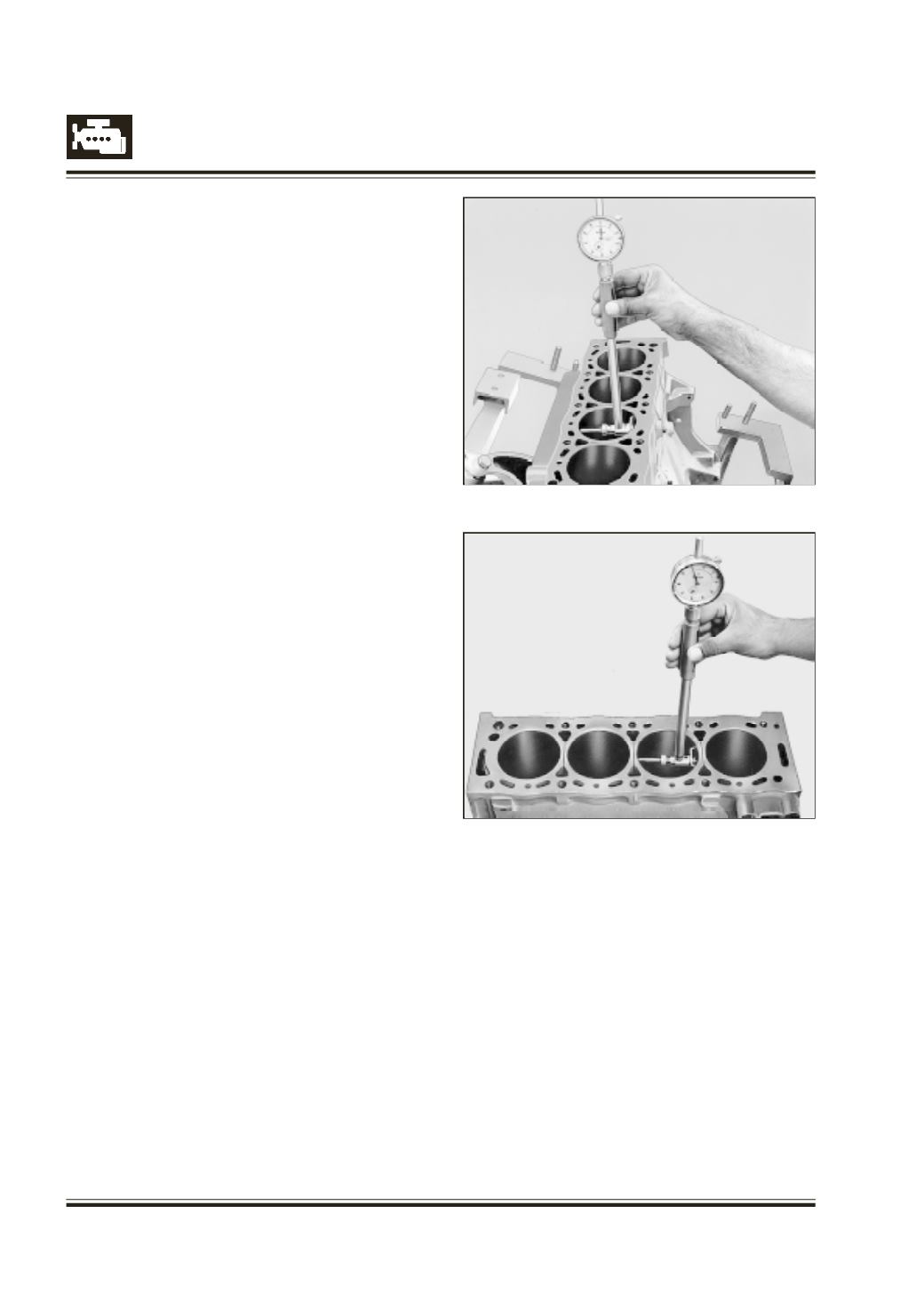
CYLINDER BORES
C
lean cylinder bores thoroughly.
C
heck cylinder bore dimension, taper and ovality.
Refer Figures. 74 & 75
I
f taper and ovality is found to exceed specified limit
or bore is excessively worn out machine cylinder bore
to next over size.
S
election of size to which bore should be machined
should be choosen as per following parameters :
- Bore diameter of worn out cylinder bore
- Size of next piston available
- Recommended clearance between piston and bore
- Required bore diameter
M
achine all bores leaving 0.050 to 0.070 mm stock
for honing.
IT IS VERY IMPORTANT THAT AXIS OF CYLINDER
BORESAREPARALLELTOEACHOTHERANDARE
AT RIGHT ANGLE TO AXIS OF CRANK SHAFT.
T
herefore we recommend use of pillar type boring and
honing machines.
C
lean cylinder bores, bearing surface and oil passages
in crank case thoroughly.
C
heck water jackets and oil passages for leakages/
cracks at air pressure of 5 bar under water.
A
pply grease tomachined surfaces especially if engine
assembly is not be taken up immediately.
Fig. 74
Fig. 75