


 741 / 1526

34
BODY
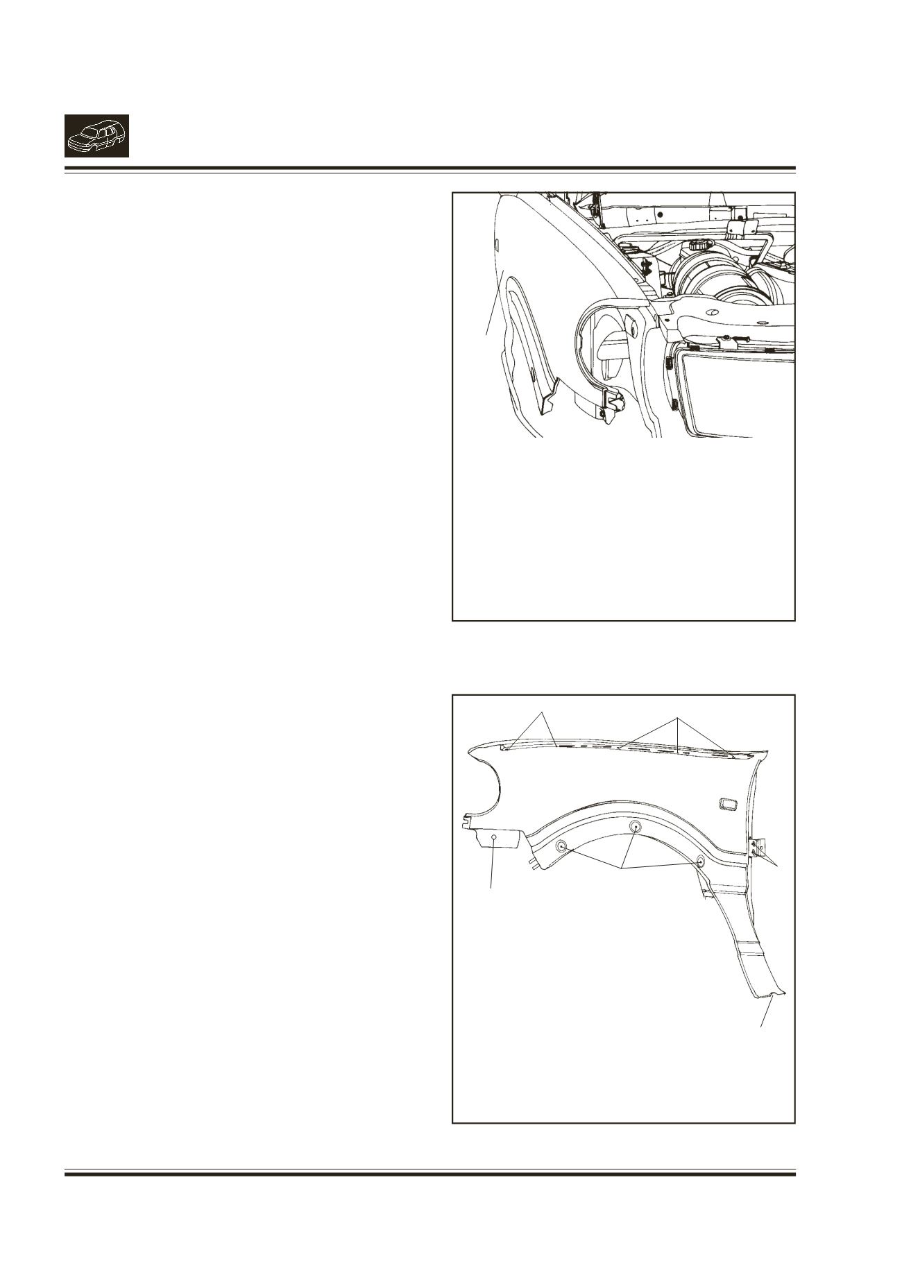
14. REMOVAL/INSTALLATION OF FENDER
(Fig. 19 & 20)
REMOVAL
l
Open the bonnet.
l
Disconnect side indicator connection and remove
the side indicator lamp by removing the spring
clip from under bonnet at RH and LH sides.
l
Remove the front bumper. Refer “Removal/
Installation of front bumper”.
l
Remove the side mould over the wheel arch.
Refer removal installation of plastic moulds.
l
Remove the rubber pads on fender top channel.
l
Remove the mounting screws on fender (five on
top, one front screw, one rear bottom screw and
two rear middle screws) and remove the fender.
INSTALLATION
l
Mount the fender in position and fix the mounting
screws.
l
Fit the side mould on wheel arch.
l
Fix the side indicators by securing the spring
clips.
l
Mount the front bumper. Refer 'Removal/
Installation of front bumper'.
l
Fix the rubber pads on top fender channel for
supporting bonnet.
Fig. 19.
1.
FENDER
Fig. 20.
1
1.
LOCATION OFTOP MOUNTING SCREWS
2.
LOCATION OF FRONT MOUNTING SCREW
3.
LOCATIONOF REAR BOTTOMMOUNTING
SCREW
4.
LOCATION OF REAR MIDDLE MOUNTING
SCREWS
5.
BUTTON LOCATION FOR MUD FLAP
1
2
3
4
5
1