


 694 / 1526

44
ELECTRICALS
17D. FRONT WIPER CONTROLLER
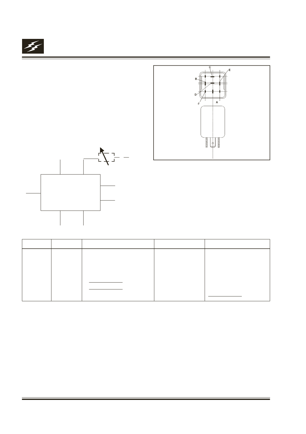
Fig. 47
Function
It generates the variable time delay during the
Intermittent wipe operation of the wipers on the
vehicle.
Location
Behind glove box on fire wall.
Connection details
Performance check
l
When the intermittent input (Ter. D) goes high,
Ter. A should get connected to Ter. B for one
wipe cycle (The unit assumes the wipe cycle is
completed when Ter. C goes to GND from VCC
level). Then for time 't' seconds (the time should
vary from 2 to 15 second with the resister R
varying from 0 to 64 K) Ter. A and B should be
disconnected. Again Ter. A and B get connected
for one wipe cycle. This cycle continuous until
Ter. D is high.
l
When wash input (J) becomes active output Ter.
A should get connected to terminal B after 0.7
sec. and when Ter. J goes low Ter. A get
disconnect from Ter. B after 2 sec. The wash
should have higher priority than the intermittent
signal.
l
When the Ter. H is low the wash function should
be ignored.
Ter. Name Ter. Type Description
Active Level
Condition
H Input
Water level sensor
GND
Water level low
J
Input
Combi switch - wash
VCC
Sw. operated
D Input
Combi switch - intermittent
VCC
Sw. operated
C Input
Wiper motor park Sw. Com.
VCC/GND
Wiper moving/Wiper park
B
Supply
VCC
I/G position
E
Ground
GND
Permanent
A
Output
Park to combi switch
VCC
Fig. 47
l
l
l
l
l
l
l
l
A
D
R
+ VE 12 V
B
E
H
C
J
WIPER
CONTROLLER