


 700 / 1526

50
ELECTRICALS
Fig. 56
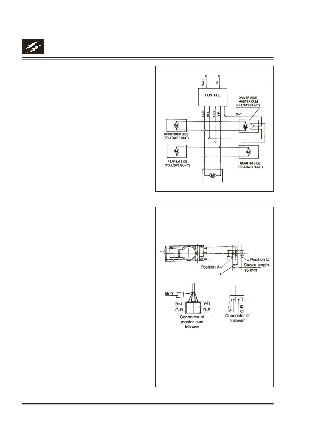
Fig. 57
18. CENTRAL LOCKING SYSTEM
Fig. 56
This vehicle has a single key for operating ignition,
steering lock, glove box and doors.
All the four doors and rear door have electrically
operated central locking system.
With central locking system all the doors can be
locked or unlocked from out side with the key or
by remote (if fitted).
From inside, the doors can be locked or unlocked
by operating the knob on the side door.
The system consists of master cum follower at
driver side door and one follower each at co- driver
side door, rear doors RH/LH, tail gate and a control
module.
Preliminary checks
Carry out the following preliminary checks as per
given order before starting the repairs.
l
Check fuse. Replace blown fuse, if any.
l
Check battery condition and state of charge.
Recharge or replace battery as required.
l
Check all related electrical connections including
earth connection for cleanliness and proper
gripping. Check specially the control unit earth
connection. Rectify as required.
l
Operate driver’s side door lock from inside and
outside and check functioning of central locking
system. Locate the faulty unit and carry out repairs
as given in subsequent paras.
l
If the central locking system is found inoperative
in total, check for the power supply at control box
input end.
If this is OK, remove the control unit and check
for proper functioning on the rig.
(Note: A simple test rig as per circuit diagram can
be made to check proper functioning of various
electrical aggregates of central locking system.
Fig. 57)
Removal of Master cum follower unit/ Follower
unit
a) Take the door window glass, in upper most
position.
b) Remove door inner trim. Refer body group. Open
out required portion of plastic membrane.
Circuit Diagram
Master cum follower unit/
Follower unit
* For master cum follower unit, the changeover
of sensor switch contacts takes place at 8 +0.5
mm from position A while travelling in either
direction (from A to D or from D to A). Position
D indicates lock position.
UNIT
TAILGATE
(FOLLOWER UNIT)