


 667 / 1526

17
ELECTRICALS
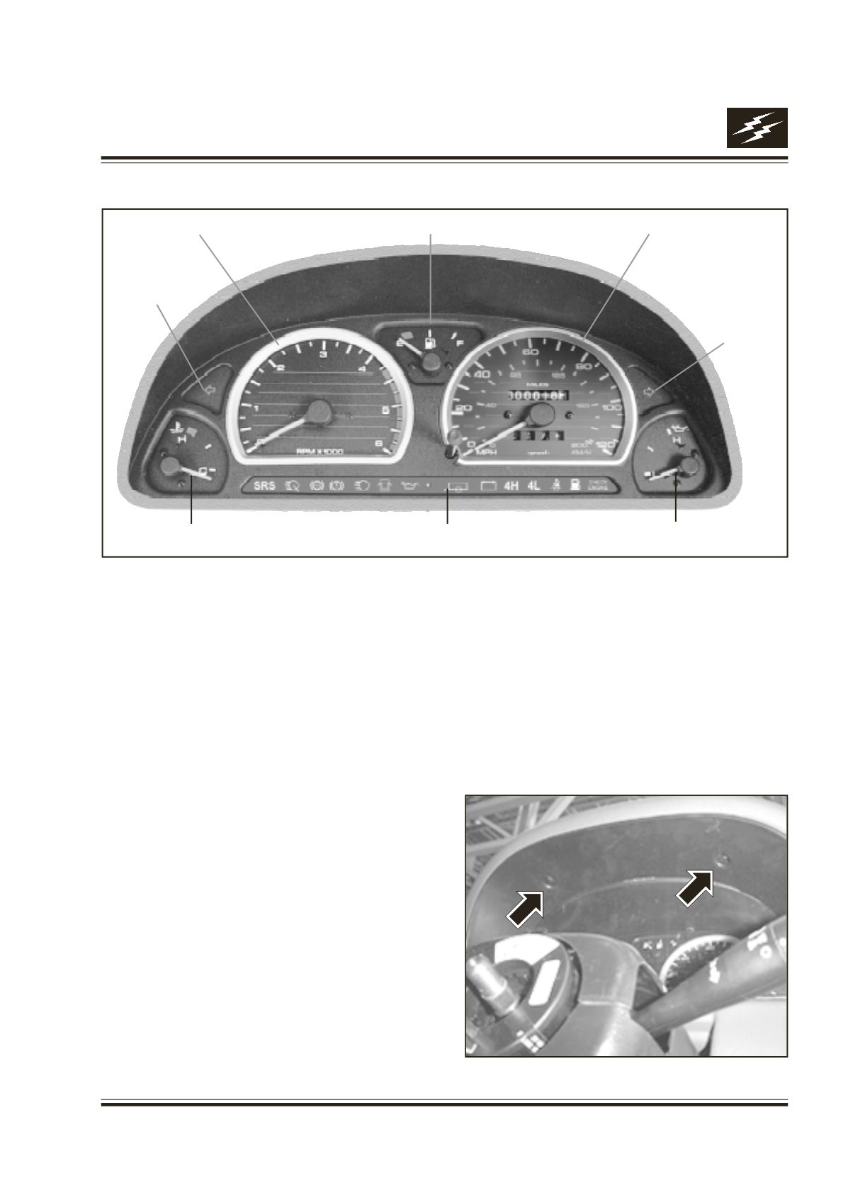
Fig. 10
Removal :
1. Remove the bezel. Fig 10
2. Push the cluster from the back.
3. Remove speedocable by breaking the seal.
4. Remove electrical connector.
Fitment :
1. Insert the unlock cage nuts in locating points on
dashboard.
2. Fit the mating connectors of W/H cabin in
respective cavities of Inst. Cluster.
3. Lay the speedocable and assemble at meter end
and seal it by crimping the lead seal on the wire
lead.
4. While pulling the speedocable from bottom, insert
the inst. cluster in the dash board cutout.
5. Align the axis of 3 mounting points of bezel on
holes provided on armature, fix the bezel by
tightening the fasteners.
6. Ensure 2mm gap between lens surface and bezel
Oil Pressure Gauge
Temperature Gauge
RPM Meter
Fuel Gauge
Speedometer*
Right Turn
Indicator
Left Turn
Indicator
Indicators
8. INSTRUMENT CLUSTER :
Fig. 9
(* Miles - Indication for export only)