


 546 / 1526

ABS
18
ANTI-LOCK BRAKES
5. COMPONENTS OF BOSCH ABS 5.3 SYSTEM
ABS for Safari is Robert Bosch ABS 5.3, 3-channel
system suitable for Parallel (Vertical) split brake
configuration.
It consists of following components :
l
Control Unit (ECU along with EBD program)
l
Hydraulic Pressure Modulator
l
Wheel Speed Sensors (front & rear, 1 per wheel)
l
Acceleration Sensor
l
Red warning lamp on the control panel, which
stays on continuously in case of ABS failure.
l
Diagnostic socket for tester.
l
EBD warning lamp which is same as parking
brake lamp.
Electronic Control Unit (ECU)
Solid state electronic device containing computer
functions, sensor signal processing circuits, output
device drives for the various ABS valves &
components and Failure Detection Logic.
The ECU is integrated in a single package with the
Hydraulic Unit (HU). It has 2 Micro controllers, which
utilize the same program for independent data
processing and monitoring functions. One of the Micro
controllers has an EEPROM to retain memory data in
case battery supply is interrupted. The EEPROM is a
nonvolatile data storage device employed to store error
codes, which can be read out for diagnosis.When an
error is encountered ABS switches itself off and triggers
the ABS warning lamp. An independent module
controls the solenoid valve relay and return pump
motor. This module supplies a stabilized voltage,
monitors micro controller operations and triggers the
ABS lamp in response to malfunction.
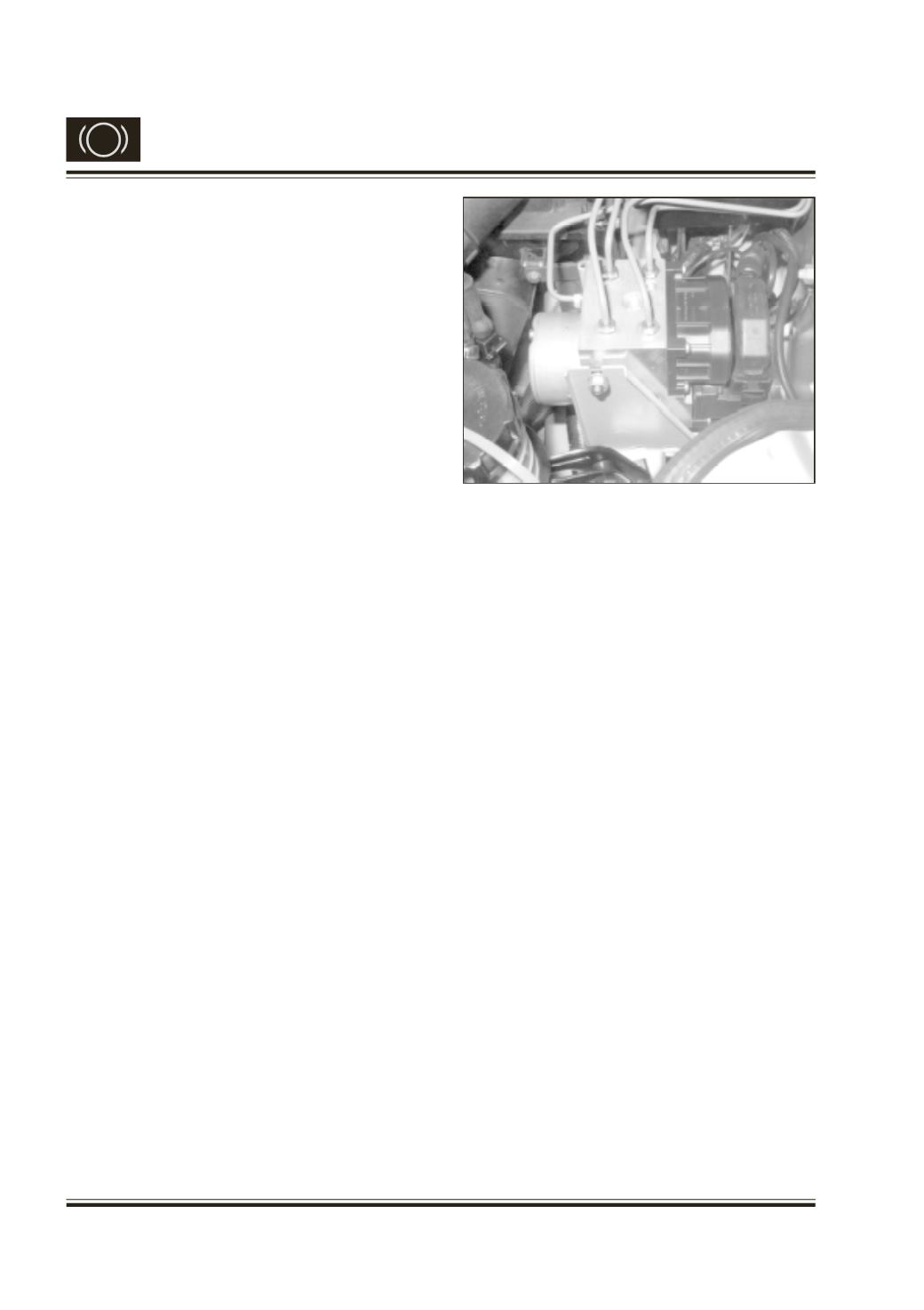
Brake Pressure / Hydraulic Modulator
An Electro-hydraulic device for reducing, holding &
restoring pressure to one or more wheel cylinders,
independent of the brake pedal effort applied by the
driver. It consists of a Return Pump, Solenoid Valves,
Damping Chamber, Accumulator, Non-Return Valve
and Motor. It forms the link between the TMC and the
foundation brakes. It implements the commands
issued by the ECU by using solenoid valves to control
the pressure at the foundation brakes.
Fig. 9
There are three pairs (3-channel system) of Inlet and
Outlet valves are located in the upper section of the
modulator. Solenoid valves that are responsible for
modulating the pressure in the brake cylinder during
active ABS control.
Each front wheel has one individual pair of inlet and
outlet valves. Both the rear wheels share one pair of
inlet and outlet valves. Incase one of the rear wheels
is on low
m
/ grip surface, the pressure corresponding
to that wheel is maintained on the high
m
/ grip surface
also to prevent wheel locking due to limited slip
differential.
The Return Pump element is installed in the center of
the modulator and is driven by an electric Motor. The
pump transfers the brake fluid emerging from the wheel
brakes through the accumulator on its way back to
the TMC through damping chamber. The pump
actuation can be felt on the foot pedal as pulsations.
In order to prevent damage to the TMC primary seals
from the compensating port, the design of TMC is
changed to central valve type (CV/CV)
Accumulator and Damping Chambers are Located in
the lower section of the hydraulic modulator. The
accumulator absorbs the surge in brake fluid that
accompanies the pressure reduction phase. The
Damping Chamber suppresses pressure oscillations
within the hydraulic system, preventing them from
being propagated back to the brake pedal and reduces
noise levels in the system.