


 543 / 1526

15
ANTI-LOCK BRAKES
ABS
BRAKINGWITH ABS INTOOPERATION
DESCRIPTION OF OPERATION OF THE
ANTI-LOCK BRAKING SYSTEM
On the basis of the signals received from the rpm
sensors located on the front and rear wheels, the
electronic control unit instructs the hydraulic unit,
so as to vary the pressure of the brake fluid
delivered to the brake calipers & wheel cylinders
passing through the three stages described below:
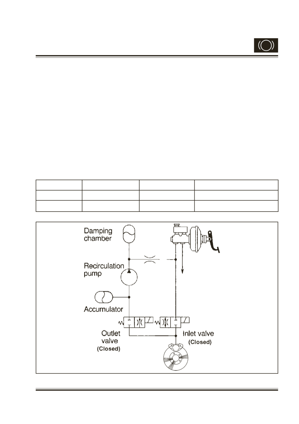
A. Pressure Maintaining (Hold) Phase
During any panic braking situation, whenever the
wheel tends to lock (because of the higher brake
pressure than optimum). ECU instructs Hydraulic
Unit to block the brake pressure coming from Master
cylinder, so that no further pressure gets into wheel
cylinder. (Refer Fig.6)
By default, the inlet solenoid valve remains open &
the out let solenoid valve remains closed. These
are the positions of the valves under unexcited
condition.
During the pressure maintaining phase, ABS ECU
actuates only the inlet solenoid valve (EV) & there
by closes it. The outlet solenoid valve remains
closed in its default position. Since both the solenoid
valves are shut the liquid channel is interrupted.
The pressure channel is closed, so that further
increase of pressure in the brake circuit is
obstructed. Non return valve mounted in parallel to
the inlet valve helps in speedy reduction of pressure
when brake pedal is released.
Solenoid valve
Electricity status
Valve open-close
Open-close channel
INLET
ON
CLOSE
Master cylinder-Wheel cylinder
OUTLET
OFF
CLOSE
Wheel cylinder-reservoir
Fig. 6