


 552 / 1526

ABS
24
ANTI-LOCK BRAKES
Removal of Electronic Control Unit (ECU)
1.
Turn OFF the ignition switch.
2.
Disconnect ECU wiring harness connector (Pull
the locking tab 1 & lift the connector) from
Electronic Control Unit (ECU) assembly.
3.
Never apply a 12V-power source to any
terminal of the ECU connector when it’s
disconnected.
4.
Identify the brake pipes going into and out of
the Hydraulic Unit (HU) with tags so that
reinstallation of the brake lines will be easy.
5.
Clean the top of the HU with a clean, dry cloth.
6.
Proper care should be taken before
removing the brake pipes from HU; the HU
must be thoroughly cleaned to prevent dirt
particles from falling into the ports of HU
or entering the brake pipes.
7.
Remove the brake pipes from the HU and plug
the ports with suitable grommet.
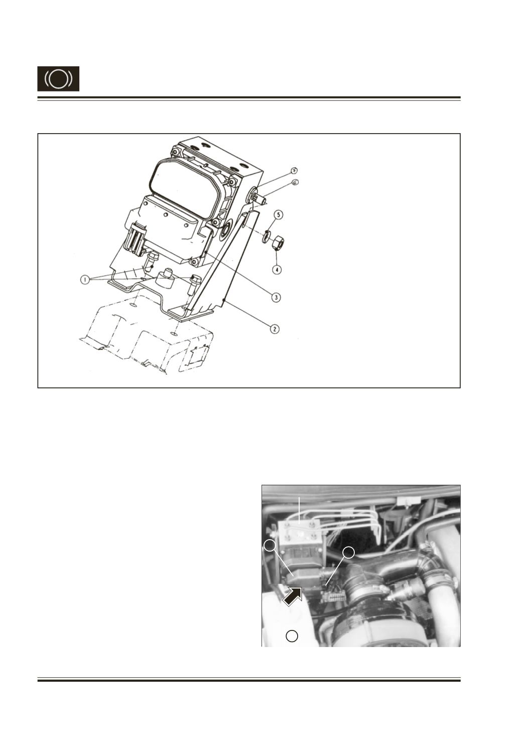
Fig. 17
Fig. 16 ABS ECU & Bracket
8.
Remove the Nuts attaching ECU / HU to the
mounting bracket and then take out the ECU/
HU from ECU / HU mounting bracket.
9.
Visually inspect the ECU ports, grommets etc.
If grommet is found damaged replace it with
new one.
8. REMOVAL / INSTALLATION OF ABS COMPONENTS
1 HEX FL. SCREW M6 X 16 TS :
17130
2 ASSY. BRACKET (FOR BOSH
ABS MTG.)
3 ASSY. HYDRAULIC
MODULATORWITH OIL - (ABS)
4 HEX NUT M8 IS : 1364 P3
5 SPRING WASHER B8 IS : 3063
6 GROMMET FOR ABS ECU / HU
MOUNTING
7 STUD FOR ABS ECU / HU
MOUNTING.
ABS Hydraulic Unit
ECU
Connector
1
2
2