


 541 / 1526

13
ANTI-LOCK BRAKES
ABS
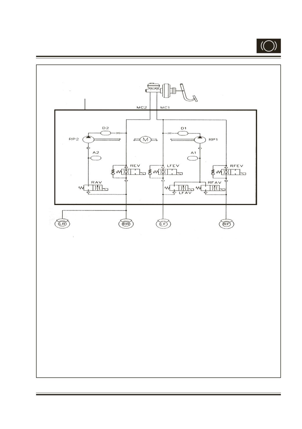
Fig. 4 ABS Hydraulic Lines Schemetic Circuits
MC1 & MC2
: Primary & Secondary brake circuits respectively.
REV & RAV
: Inlet & outlet solenoid valves of Rear wheels
LFEV & LFAV
: Inlet & outlet solenoid valves of Front Left wheel
RFEV & RFAV
: Inlet & outlet solenoid valves of Front Right wheel
A1 & A2
: Accumulators of the circuits MC1 & MC2 respectively.
RP1 & RP2
: Recirculating pump of the circuits MC1 & MC2 respectively.
M
: Motor for driving recirculating pumps
D1 & D2
: Damping chambers.
O1 & O2
: Orifices
NRV1, NRV2, NRV3 : Non return Valves of Front right, Front left & Rear wheels
respectively.
O2
O1
NRV3
NRV2
NRV1
Hydraulic Unit