


 40 / 1526

11
4 DLT ENGINE
VISCOUS FAN DRIVE
Operation of the viscous fan drive.
The viscous drive unit for the engine cooling fan
provides a means of controlling the speed of the fan
relative to the temperature of the engine.The viscous
fan unit, see Figure 6. is a type of fluid coupling, which
drives the fan blades by means of 'silicon fluid'.
Operation :
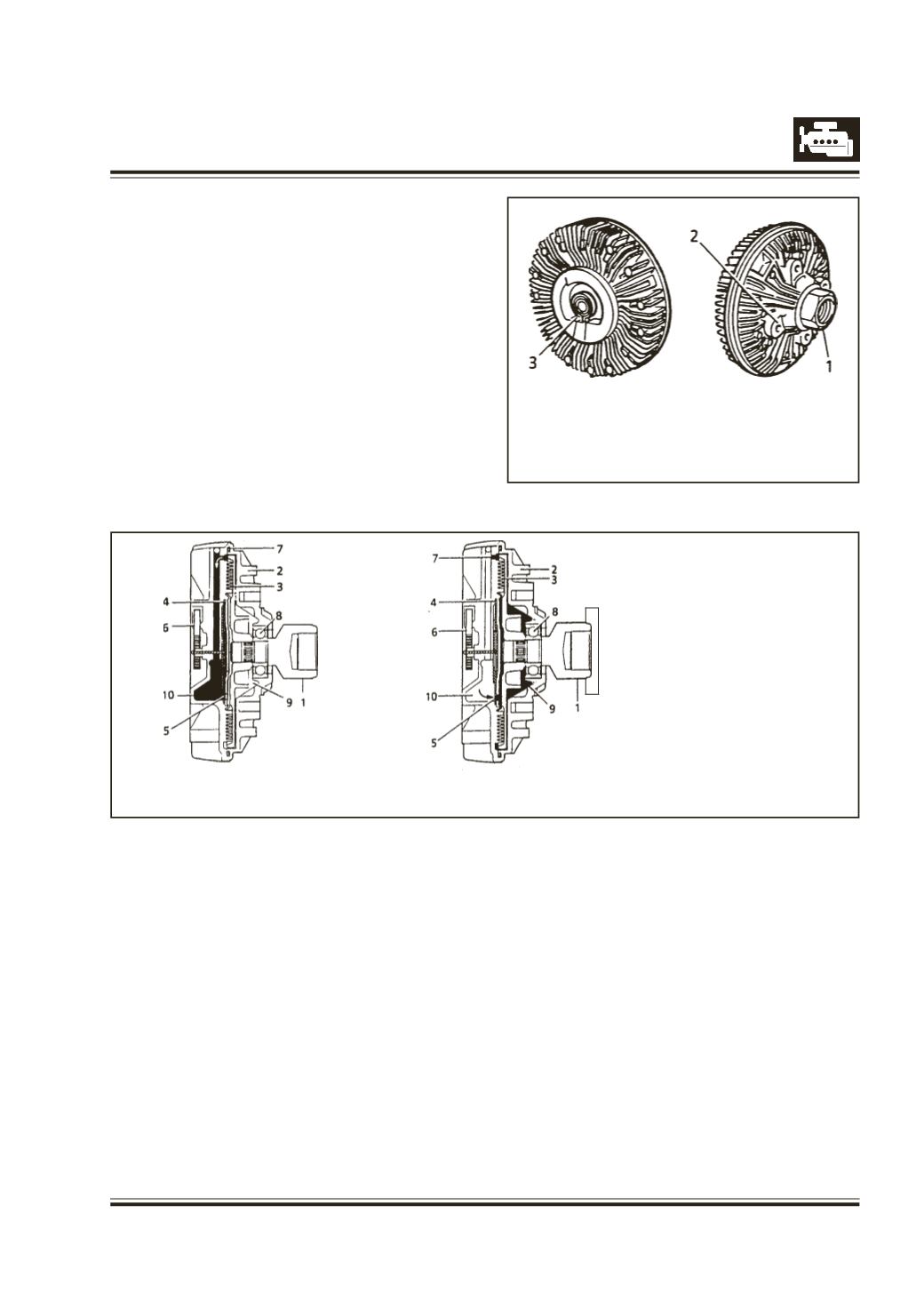
There are two main components of the viscous
fan drive : An input (drive) member (1) consisting
of a threaded shaft passing through a bearing
into the clutch plate and secured to the water
pump, see Figure 7. An output (driven) member
(2) comprises the main body to which the fan
attaches, with the temperature sensing
1.
Input (drive) member.
2.
Output (driven) member.
3.
Running clearance.
4.
Pump plate
5.
Valve (closed)
6.
Sensing mechanism
(bi-metal coil)
7.
Fluid seal
8.
Bearing, input member
9.
Fluid chamber
10. Fluid reservoir
Fig.6
Fig. 7
Viscous unit disengaged (engine at
normal operation temperature)
mechanism (bi-metal coil) (6) and pump plates
(4).
The fan drive has to be engaged only periodically,
between 5% and 10%, during normal operating
conditions because the rest of the time the
vehicle cools itself by ram air cooling.
To engage and disengage the fan drive the bi-
metal coil senses air temperature behind the
radiator.When a pre-determined temperature is
reached, the coil opens a valve (5) which allows
fluid to enter the drive area and due to centrifugal
force circulates to the annular drive area. There
are two sets of annular grooves (3), one in the
drive clutch and the other in the drive body, a
specific clearance being provided between the
two sets of grooves.When this clearance is filled
with viscous fluid a shearing action, caused
by the speed differential between the two drive
components, transmits torque to the fan.The fluid
is thrown to the outside of the unit by centrifugal
force from where it is then re-circulated to the
reservoir (10) via the pump plate 4 adjacent to
the drive member.
If the engine speed is increased the amount of
slip will also increase to limit the maximum fan
speed.
When the air temperature from the radiator drops
sufficiently, the bi-metal coil closes the valve
and prevents fluid entering the drive area, See
Fig. 8 The fluid that is in the drive area will
gradually pump out into the reservoir (10) and
the fan will return to an idle condition.
Fig.8
Viscous unit engaged (hot running temperature)
Bi-metal coil (6) expanded, valve (5) open.
1.
Input (drive) member
2.
Output (driven) member
3.
Sensing mechanism (bi-metal coil)