


 362 / 1526

30
SUSPENSION
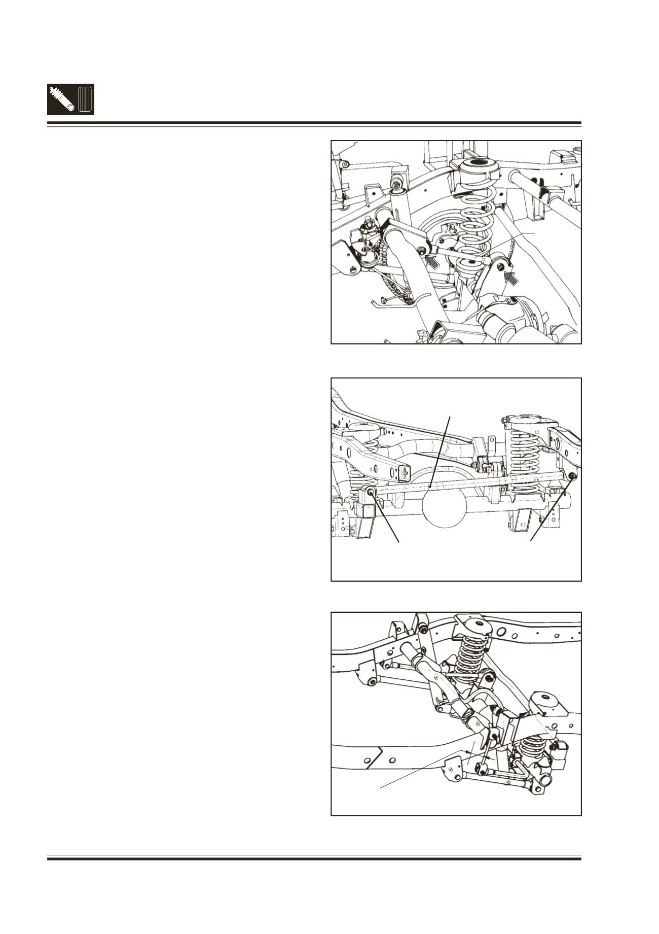
c) ASSEMBLY / INSTALLATION OF TOP LINK
l
If rubber bushes have been removed earlier, refit
new bushes, using suitable drift.
l
Install the top link assembly in position, tighten
the bolts to 16 mkg torque (Fig.35).
d) ASSEMBLY/INSTALLATION OF PANHARD
ROD
l
If rubber bushes have been removed earlier, refit
new bushes, using special tool (Part No. 2658
5890 32 02.)
l
Install the panhard rod in position and tighten
the bolts to 16 mkg torque. (Fig.36)
The offset should be opposite to rear axle
housing.
e) INSTALLATION OF ANTIROLL BAR
ASSEMBLY
(Fig.33)
l
Position antiroll bar between two links
l
Install bearing block on antiroll bar
Note
Apply silicon grease molicote 33 (Medium) on
antiroll bar over bearing width before fitment of
bearing block.
Install hex bolts and nyloc nuts connecting
antiroll bar with links. Tighten nyloc nuts to
4 mkg. torque.
l
Locate bearing block on rear axle
l
Install, brake pipe support and LCRV Spring
mounting bracket alongwith hex bolt, spring
washer and bright washer on bearing block
(Fig.33). Tighten hex bolts to 4.5 mkg. torque.
l
Ensure gap 15 mm between long member and
link rod at both RH & LH side (Fig.37).
f)
INSTALLATIONOFREARSHOCKABSORBER
(Fig.34)
l
Install the shock absorber in position. Ensure
that at top of shock absorber mounting, chamfer
of washer to be towards corner radius of
mounting pin.
l
Tighten the Nyloc nuts of shock absorber
mounting to 6-7 mkg torque.
Fig. 35 - Installation of top link
Fig. 36 - Installation of panhard rod
Fig. 37 - Gap between long member and link rod
TOPLINK
PANHARDROD
HEX. BOLT M 16 x 1.5 x 90
NYLOC NUT M 16 x 1.5
TORQUE - 16 mkg.
HEX. BOLT M 16 x 1.5 x 90
NYLOC NUT M 16 x 1.5
TORQUE - 16 mkg.
ENSURE GAP BETWEEN LONG MEMBER AND
LINK ROD OF REAR ANTIROLL BAR TO BE 15
MM. MINIMUM AT THE BOTH R.H. AND L.H. SIDE.