


 358 / 1526

26
SUSPENSION
4D. REMOVAL OFTOP LINK
(Fig. 29)
l
Support the front wheels with wheel chocks to
prevent the vehicle from any movement.
l
Jack up the chassis frame at the centre of
vehicle on both sides (RH & LH) such that there
is no load on the top link mounting bolts.
l
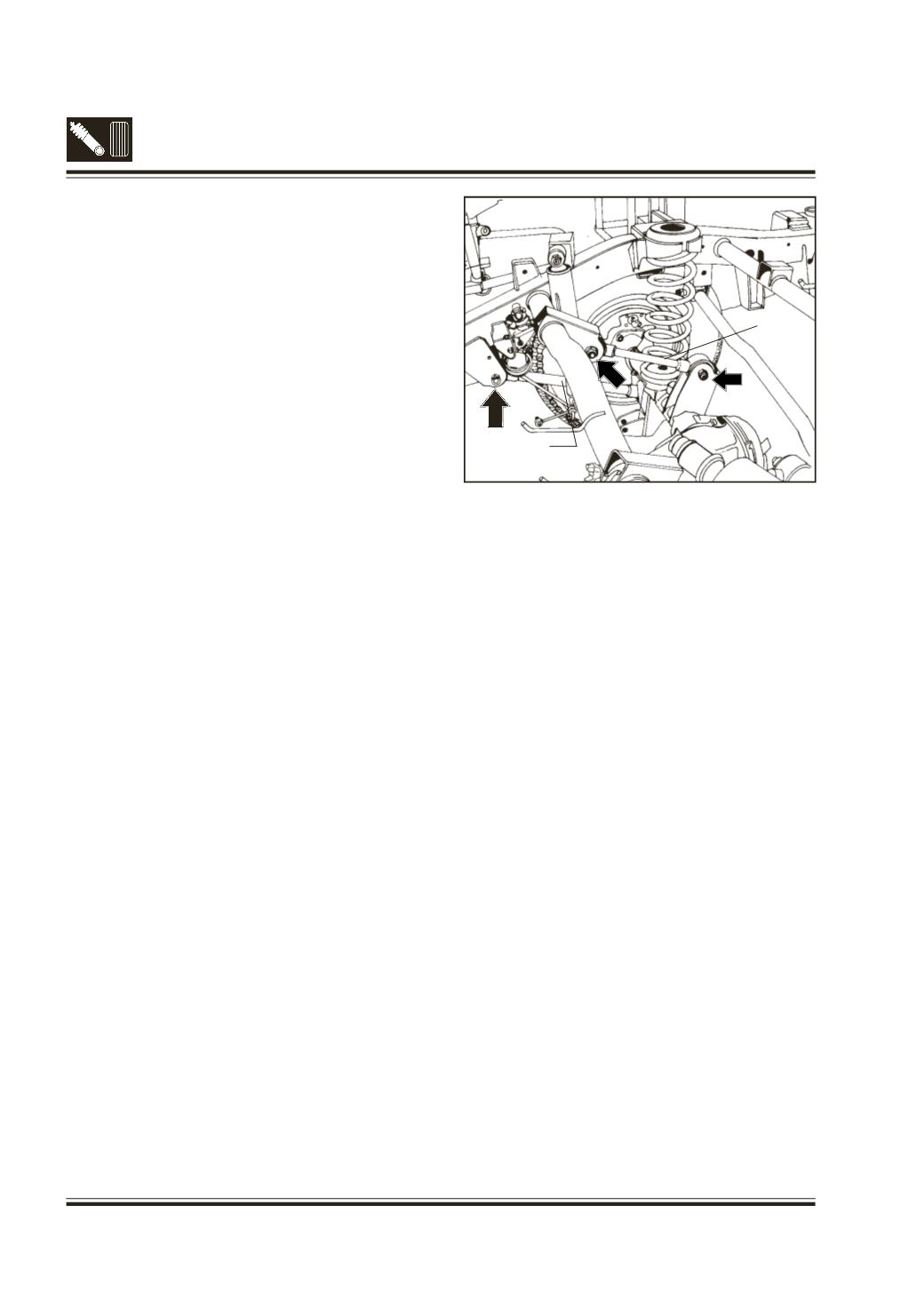
Loosen & remove the nuts of top link mounting.
(Fig. 30)
l
Tap out & remove the bolts.
l
Take out the Top links.
4E. REMOVAL OF REAR COIL SPRING
(Fig. 29)
l
Jack up the frame long member to such an
extent so that coil spring is released of
compression fully.
l
Take out the coil spring.
l
Take out the spring seat top.
4F. REMOVAL OF BOTTOM LINK
(Fig. 29)
l
Disconnect the propeller shaft by removing
universal joint strap mounting screws at the tail
pinion and tie it suitably to chassis long member.
l
Disconnect the parking brake cable of LH side
at the link end.
l
Loosen and remove the nuts of Bottom link
mounting. (Fig. 30)
l
Tap out and remove the bolts.
l
Take out the Bottom links.
Fig. 30 - Removal of top link and bottom link
BOTTOMLINK
TOPLINK