


 141 / 1526

102
4 DLT ENGINE
EGR SYSTEM (If fitted)
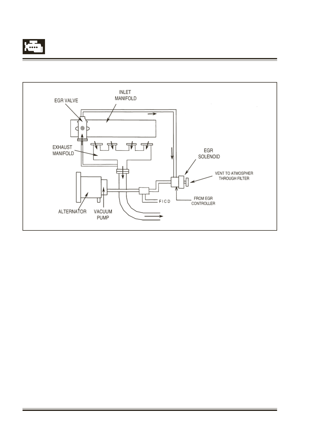
Fig. 191 Schematic diagram of EGR circuit on Safari Euro - III Engine
Exhaust Gas Recirculation
The basic purpose is to tap out a part of exhaust gas
from the exhaust manifold and mix with the intake air
of the engine in part load and part speed conditions
thus reducing the amount of harmful pollutants.
Please note that during cold starting till the glow plug
remains on, the EGR system does not function thus
avoiding any hunting or vibration at initial start
conditions.
SystemComponents
EGR CONTROLLER :
The EGR system of the vehicle is controlled more
precisely based on engine speed, throttle lever
position.
The EGR CONTROLLER is mounted on the firewall
inside the engine compartment.
EGRValve (EGR-V)
The EGR valve is a diaphragm valve that is actuated
by vacuum from the Vacuum Pump. The valve is
mounted on the inlet manifold. It has three
connections, one for the vacuum, one for the exhaust
gas inlet from the exhaust manifold and one for the
exhaust gas outlet to the inlet manifold. The exhaust
gas starts flowing into the inlet manifold once the
vacuum is fed into the valve.
EGR Electro pneumatic solenoid switch
Note
: Care should be taken to connect the ports of
the Electro pneumatic solenoid switch to their
respective hoses. Any interchanging of the
connections will lead to malfunctioning of the EGR
system. Additionally, existence of small filter with
foam needs to be ensured on the connection open to
atmosphere.
EGR pipe
:
This pipe connects the exhaust manifold to the EGR
valve.
Exhaust / Inlet Manifold
The exhaust manifold has a precisely machined hole
through which the exhaust gases are tapped out.