


 1399 / 1526

16
4 PL FUEL SYSTEM
EVAPORATIVE EMISSION CONTROL
SYSTEM :
The car is fitted with an evaporative system to meet all
requirements of evaporative emission.
The system is designed to prevent fuel vapours formed
within the tank and fuel system from escaping into the
atmosphere.Theevaporativeemission systemconsists of :
a) Restrictor
b) Vapour Separator
c) Tank pressure valve
d) Carbon canister
e) Canister Purge valve
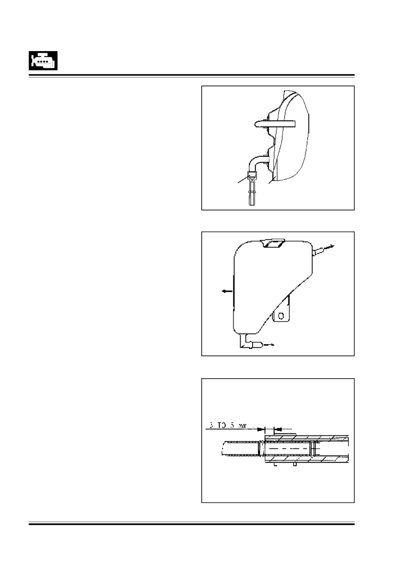
a) Restrictor : Fig. 18
The restrictor is welded on top portion of the fuel
tank assy. The restrictor allows the flow of gasoline
vapours only and not liquid fuel in both directions.
b) Vapour Separator : Fig. 19
Theseparator ismadeof highgradeof polypropylene
and is mounted near to the filler neck area on the
rearwheel arch. Avapour liquidseparator allowsonly
liquid free vapour to pass from fuel tank restrictor to
the carbon canister through tank pressure valve.The
vapours getting condensed / liquid fuel goes to the
filler neck.
Removal :
1.Toavoiddamage to the vapour hoseswhiledisconnect-
ing slideback the clamps and pull the hoses.
2.Remove quick connector’s joints carefully.
3. Loosen vapour separatormounting screws.
Inspection :
Check for crack or deformation of vapour separator.
Replace if necessary.
Assembly :
1.
Vapour hoses connections varies for each type of
hose. Necessary care to be taken to connect and
clamp each hose correctly. Use suitable tool for
fitment of clamp.
2.
Do not kink or twist hose when they are routed.
3.
For hoseconnection tovapour separator followsche-
matic circuit figure.
4.
The middle port to be connected to the restriction
on fuel tank.
5.
The port on top (port of float valve) to be connected
tounderbodyvapourlinesgoingtotankpressurevalve.
6.
The bottomport tobe connected to fuel filler neck
tube.
Fig.
Fuel Tank
Restricter Tank
Fig. 20
Fig. 19
18
To Canister
To Tank
Drain
To Tank
Restricter