


 1282 / 1526

ENGINE
114
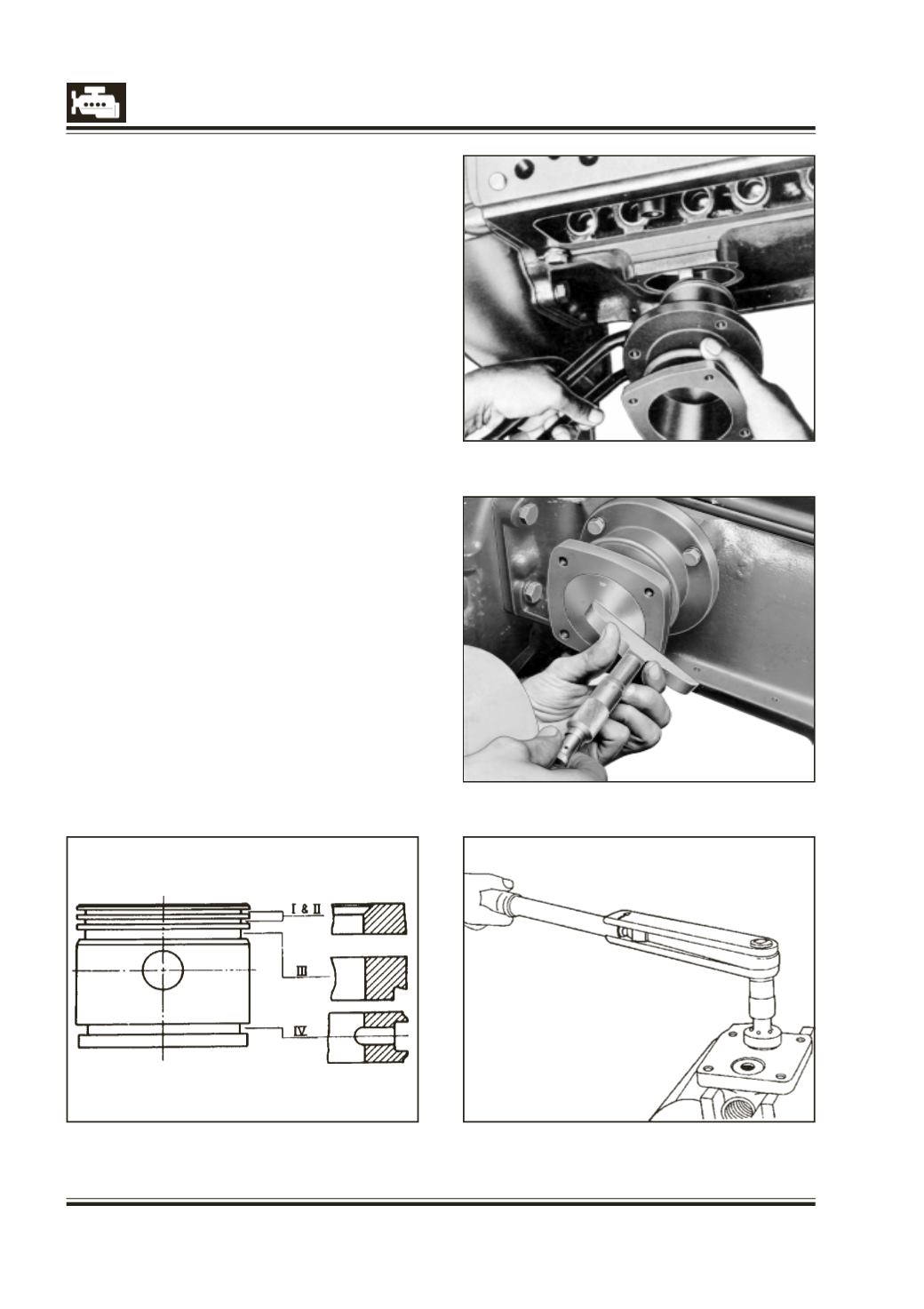
Fig. 11
Fig. 8
Fig. 9
Fig. 10
ASSEMBLY AND INSTALLATION OF
VACUUM PUMP
Fig. 6 and 7
1 Insert bearing shells into connecting rod and
connectingrodcap. Applycleanoil tobearingsurface.
2 Install connecting rod and bearing cap on camshaft
eccentric with bearing shells. Ensure locating lug of
bearing shell is on top side. Tighten to specified
torque.
3 Install piston rings on piston using expander.
Ensure that ‘TOP’ mark on 1st, 2nd and 3rd ring
faces piston crown. Fig. 8
4 Position piston on connecting rod and install
piston pin. Fit circlip.
5 Apply clean oil to piston and cylinder sleeve bore
surface. Compress piston rings with clamping strap,
2576 5890 02 09. Fig. 9. Insert cylinder sleeve over
piston.
6 Screw cylinder sleeve mounting bolts to
crankcase and tighten them to specified torque.
7 Check protrusion of piston crown from cylinder
sleeve surface with a depth gauge. Select gasket
betweencrankcaseandcylindersleevetobringpiston
protrusion within specified value. Fig. 10.
8 Unscrew cylinder sleeve mounting bolts and
remove cylinder sleeve. Fit selected gasket
between crankcase and cylinder sleeve. Install
cylinder sleeve in position. Before assembling
cylinder sleeve stagger ring gaps, so that they
are not in one line. Tighten mounting bolts to
specified torque.