


 1278 / 1526

ENGINE
110
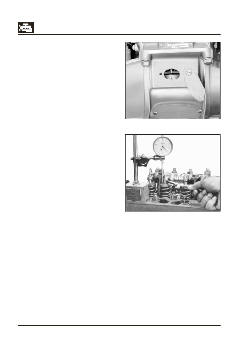
Fig. 22
Fig. 23
CHECKING VALVE TIMING
1. Attach suitable graduated disc to the crankshaft
pulley and mark ‘BDC’ position on the periphery
of the pulley by turning crankshaft by 180
0
from
‘TDC’ position. Fig. 22.
2. Remove cylinder head cover.
3. Adjust valve clearance (inlet 0.2 mm outlet 0.3
mm). Eliminate No. 1 inlet valve clearance by
inserting a 0.2 thick feeler gauge between valve
tip and rocker. Fig. 23.
4. Turn crankshaft to bring No. 1 piston to TDC
(compression stroke). In this position, valves of the
No. 4 cylinder will be overlapping.
5. Attach magnetic stand with dial gauge to the
cylinder head in such a way that the plunger of
the dial gauge rests on the spring retainer of the
1st cylinder inlet valve with a preload of about 10
mm. Position plunger on the spring retainer as
away as possible from the centre to avoid fouling
of the rocker. Adjust dial gauge pointer (bigger)
to zero and also note down the reading of the
smaller needle.
6. Turn crankshaft clockwise slowly through 360
0
to
bring No. 1 piston just to TDC II position (end of
the exhaust stroke). Do not turn crankshaft in anti-
clockwise direction to adjust TDC position.
NOTE :
Before reaching the TDC position, preloaded
plunger of the dial gauge will move along the
spring retainer of the valve. Note down dial gauge
reading when the TDC position is just reached.
7. The difference between dial gauge readings will
give valve lift. The valve timing is correct if the lift
indicated by the dial gauge is within the specified
value of 0.75 + 0.2 mm.
8. The valve timing can be counter checked by
turning the crankshaft clockwise further by 180
0
in order to bring No. 1 piston to BDC II position
(end of the suction stroke). Note down the dial
gauge reading when the BDC position is just
reached. The difference between this and the
initial dial gauge reading will give the valve lift in
this position.The timing is correct if the lift is within
the specified value of 4.25 + 0.3 mm.
9. Valve timing can also be ascertained by checking
the lift of the exhaust valve. To be doubly sure, it is
preferable to check the lift of the exhaust valve of
No. 4 cylinder. The valve lift at BDC I (end of power
stroke) and TDC II (end of exhaust stroke) should
correspond to specifications.
10. Valve lift readings beyond the specification
suggest wrong valve timing possibly on account
of worn out crankshaft-camshaft gears/damaged
woodruff keys/mismatched timing gears (i.e. ‘1’
mark on crankshaft gear tooth is not matched with
‘3 - 3’ mark on camshaft gear.
11. Identify the defect and rectify.