


 1221 / 1526

ENGINE
53
1
2
3
4
5
6
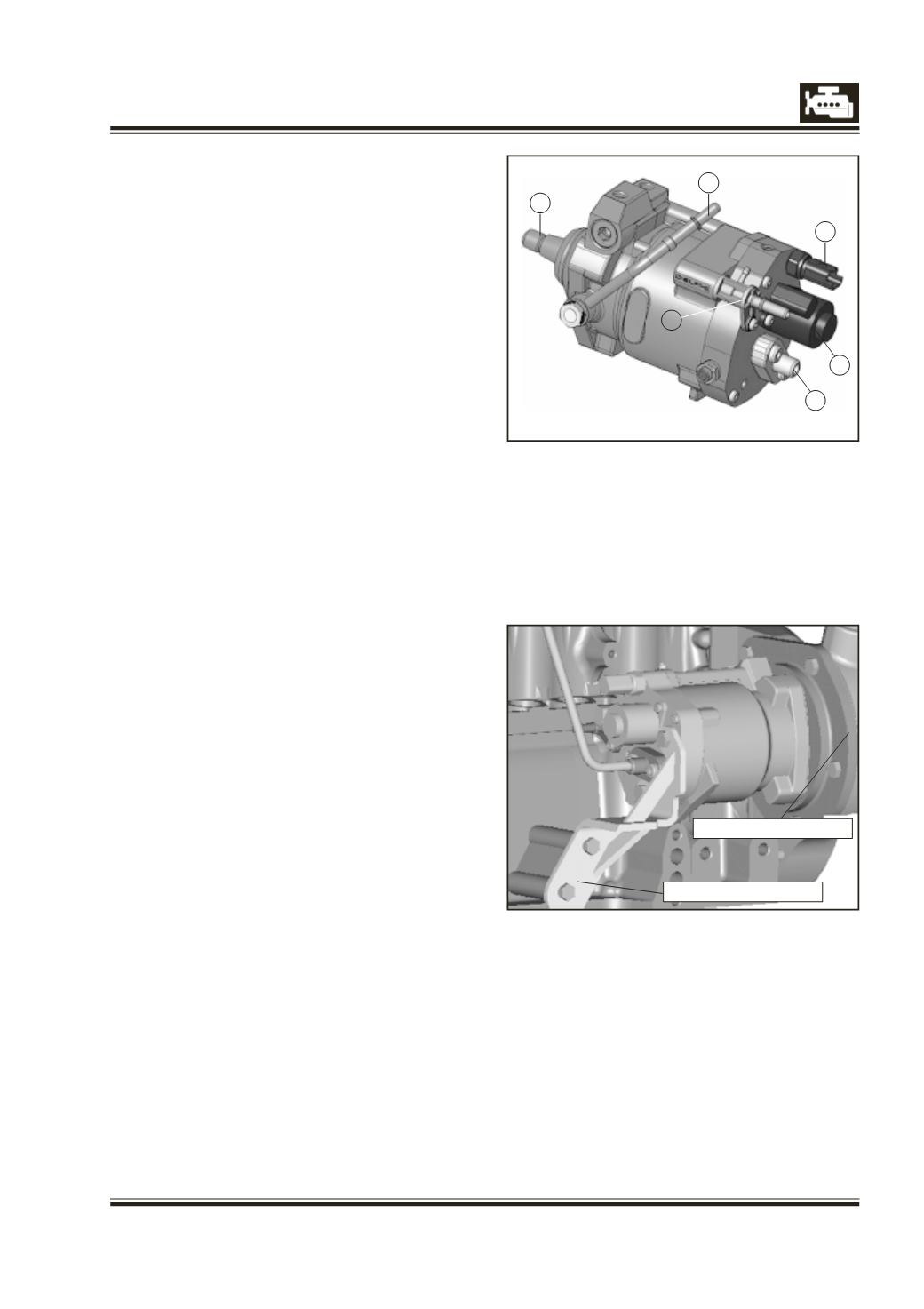
1 Pump inlet
2 Venturi
3 Fuel temp. Sensor (FTS)
4 Inlet metering valve (IMV)
5 Pump outlet
6 Drive to HP pump
Rear mtng. bracket
Front mtng.
bracket
High Pressure Pump
DFP 1.2 (4 plunger) with double driveshaft seal for
gear drive.
Technical Description
l
Gear drive – Clockwise rotation
l
Double driveshaft seal
l
Drive ratio : 0.5
l
Mounting flange with three M8 thread holes
l
Centering diameter : 68 mm
l
Hydraulic connection : no inlet screw nor banjo
l
Mechanical connection: rear bracket.
l
Fuel temperature sensor and venturi
l
Inlet metering valve (IMV)
l
Integrated Transfer Pressure Pump
l
Pressure limiter
l
Pump: 4 Plunger Pump (Multi Lobe Cams)
l
Up to 1600 bar operating pressure
l
Venturi in pump return
Lift pump
(Transfer pump)
sucks fuel from tank and provides intermediate
pressure to HP chambers.
IMV
l
Controls fuel flow into HP chamber in order to
control rail pressure
l
NO high pressure fuel is spilled from system=good
energy management
Venturi
l
Generates a depression in the fuel injector backleak
circuit
l
The depression in the injector control valve
chamber improves shot to shot
Temperature sensor
l
Measures fuel temperature in Transfer pressure
circuit
l
This information is used to modify rail pressure
control terms at extreme temperatures
Fitment
Pump fitted with a pump mounting bracket on TGH.
Rear support for arresting vibrations in pump. No
injection timing adjustment to be done in the
pump. Injection timing is programmed in the ECU.
Precaution
Ports to be plugged with caps if HP pipes or back-
leak pipes are removed.
It has to be replaced in case of serious damage
caused due to dust entry. Following is the removal
and fitment procedure.