


 1075 / 1526

35
GEAR BOX G-76
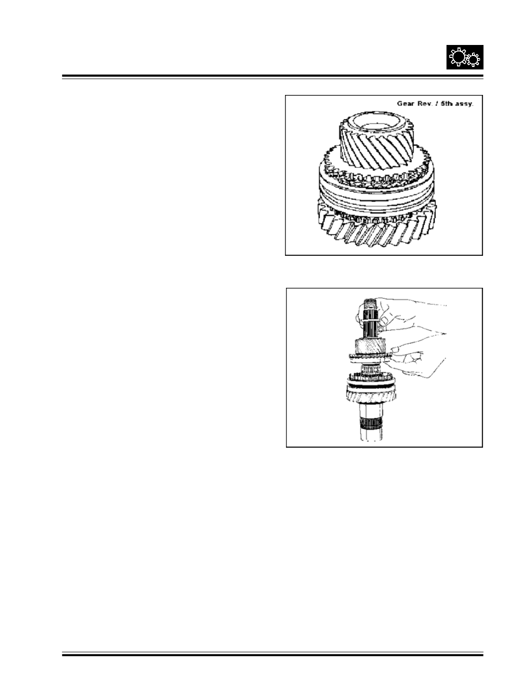
Fig. 73
ii. SUBASSEMBLY OF MAIN SHAFT
Hold the main shaft vertically keeping the coupling
flange end upwards.
Slide reverse gear sub-assembly on main shaft along
with needle roller cage and engaging gear keeping
engaging gear upwards.
Fit snap ring Select snap ring such that it is snug fit in
the groove. Snap rings are available in thicknesses
ranging from 1.7 to 2 mm in the step of 0.05 mm.
Slide the 5th gear sub-assembly along with the needle
roller cage and synchro cone such that the synchro
cone is towards engaging gear. Ref Fig. 73
Fig. 72
Note :
While assembling 3rd / 4th gear, the shifter
sleeve without groove to be fitted with broader side
towards 3rd gear.
The dual synchro cones are put in place with proper
fitting into the locking holes at the gears.
In Reverse /5th gear assembly, fit double groove side
of shifter sleeve towards reverse gear. Ref Fig. 72