
1.2L REVOTRON ENGINE
129
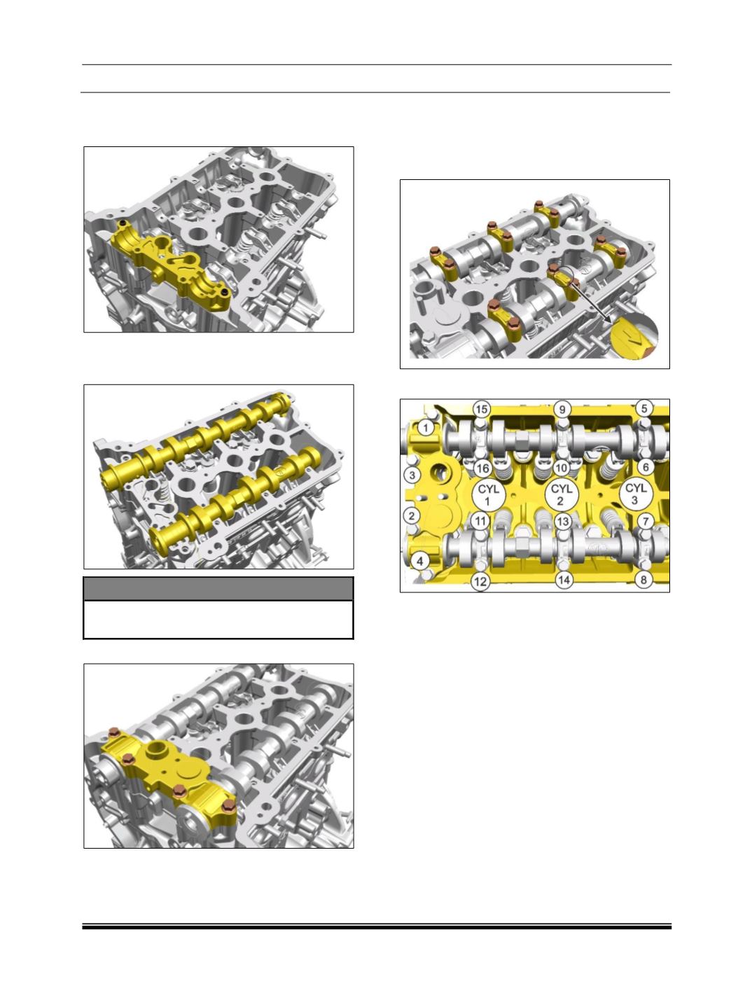
5. Assemble the lower ITG Bearing Cap with
locating dowels. Ensure the NRV (Non return
valve) in place inside lower ITG.
6. Place the camshafts to their respective
location in such way that the cam lobes of first
cylinder are opposite to each other as shown.
NOTE
Cam lobes should not be pressing any
valves.
7. Assemble the ITG Bearing Cap Upper.
8. Assemble the Cylinder Head cam cap bolts
along with the washers, starting from the ends
of the cylinder head and working inwards to
the center. (Keep the arrow of cap in outward
direction.)
9. Refer the loosening sequence.


