


 500 / 1525

25
BRAKES
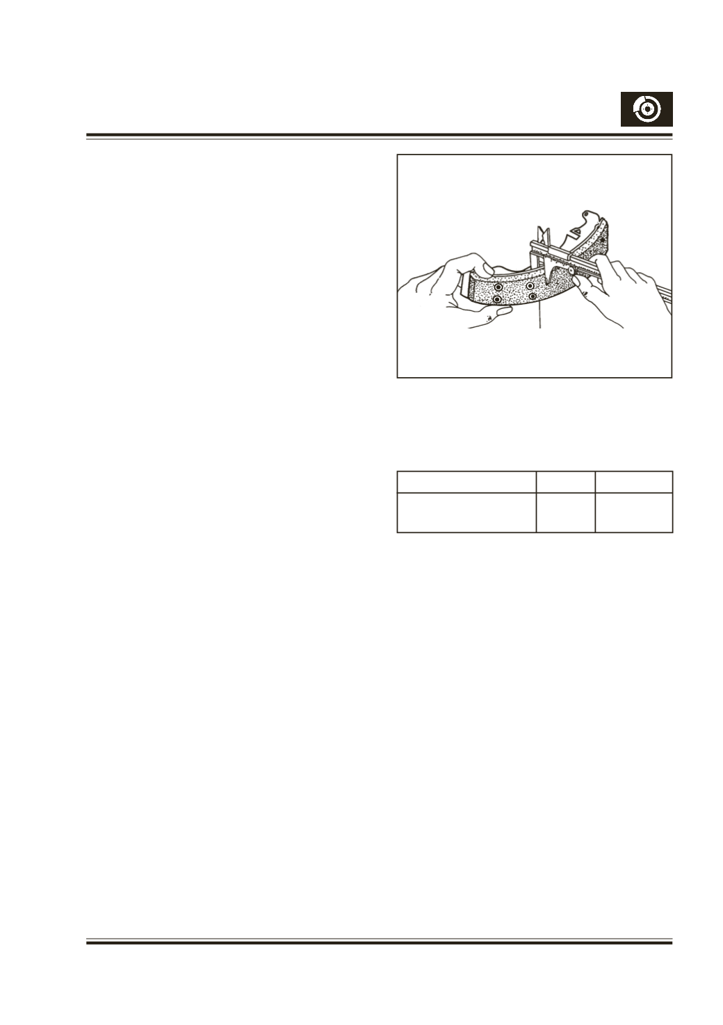
While deriveting, ensure that the holes in the
shoe rim are not enlarged.
Clean the shoe rim to ensure a smooth even surface
for the lining.
Always use genuine linings during relining,
including the rivets supplied along with the
relining kit.
Clamp the lining evenly to the shoe rim, and start
riveting at the centre and progress outwards to the
end of the shoe. A flat ended anvil of the correct
diameter should be used against the rivet head and
the tubular shank of the rivet should be properly
clinched.
Care should be taken, since over riveting may crack
the lining. Ensure that no clearance exists between
the lining and the shoe rim.
Fit the hand brake operating lever to the trailing shoe
in the reverse order of removal.
Ensure that the spring plate convex side is towards
the retaining plate.
Make sure the lever is free to operate.
Do not contaminate the lining surface with oil or
grease.
Refit the shoes in accordance with the following
instructions :
FITTING SHOES
ASSEMBLING
Lightly smear the following parts with special grease
as given. Keep the grease away from the shoe linings
and all hydraulic parts.
1) Tips of new shoes - Graphite grease
2) Hand brake strut slots - Graphite grease.
3) Adjuster Pushrod Threads - Mineral oil base
grease.
Note :
When ever relining is done or new shoe is
fitted, ensure to fit new shoe return springs also.
Always fit new shoes in pairs to both the sides of
the vehicle. (RLH and RRH sides)
Fig. 26
Do not polish lining with sand paper or emery paper. If
lining is polished with sand paper or emery paper, hard
particles of sand paper will be deposited in the lining
resulting in damage of drum surface.
Brake lining
Standard Service Limit
Lining Thickness above 3-3.9 mm 0.5 mm
(rivet head)
Refer to the illustration Fig. 15. Assemble Male (12)
and Female (9) pushrods (to its Min. length) with
adjuster nut (11) along with thermo clip (10), taking
care of the thermo clip position as shown on the
Fig.15 (Ensure to fit the thermo clip facing down for
satisfactory functioning of the auto adjuster
mechanism).
Assemble the abutment end spring (8) between the
shoes. Place the shoes, springs along with adjuster
in position on to the platforms of the back plate and
locate the spring (8) below the riveted abutment plate
and the shoes in the abutment groove. Hook the
shoe return spring (7) (short length coil) to the
leading shoe, with the adjuster assembly in its
minimum length condition, assemble the adjuster
assembly between the shoe webs. Attach the other
end of the shoe return spring (7) to the opposite end
of theTrailing shoe (3).Adjust the length of the adjuster
until the shoes will clear the wheel cylinder pistons.
Fit the pawl lever (18) to the spring dowel (20, 21, 22)
inserting one leg of the pawl between male push rod
end and shoe web of the leading shoe and the other
end of the pawl leg resting on the adjuster nut (11).
Hook the short end of the spring (19) into the hole in
SHOE LINING