


 506 / 1525

31
BRAKES
ASSEMBLING TANDEMMASTERCYLINDER
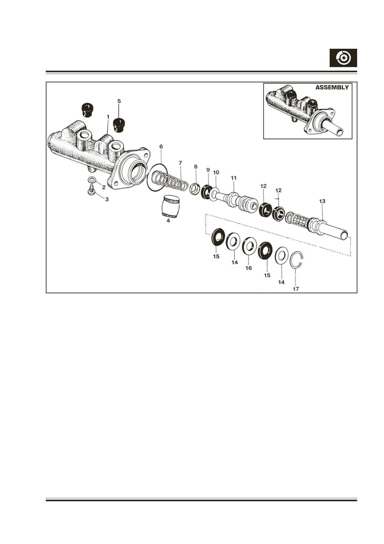
(Fig.32)
Absolute cleanliness has to be maintained and clean
fresh brake fluid must be used. Never use the brake
fluid bled from the system as it is aerated.
To facilitate easy assembly, smear the cylinder bore
with fresh brake fluid liberally. Dip the plungers and all
seals in fresh brake fluid. Fit the recuperating seals in
the secondary plunger grooves.The first seal lip facing
the primary plunger assembly and the lip of the second
seal facing the opposite side. Push the seal shim,
recuperating seal on the stem side of the secondary
plunger in such a way that the lip of the seal faces
towards the secondary spring. Fit the spring retainer
in correct position and fit the secondary spring.
Clamp the cylinder body with its mouth pointing
upwards in a vice fitted with soft jaws. Fit secondary
plunger assembly with the secondary spring leading
into the bore using seal guide. Then slowly push the
plunger down the bore, with a round ended rod. Press
it down fully and whilst holding screw in the stop pin
with a new gasket (stop pin) and tighten to a torque of
0.7 - 0.55 mkg. Slowly let the secondary plunger back
till it touches the stop screw.
Now insert the primary plunger assembly in the same
manner into the bore using the seal guide.
Fit the first stop washer on to the primary plunger
shaft. Fit the primary back seal into bush and slide
the bush on to the primary plunger shaft with the seal
in the bush leading into the bore. Now press the bush
firmly into the bore.Now insert guide on to the primary
shaft.Whilst pressing down the guide remove the bush.
Remove the guide from the primary plunger shaft.
Insert intermediate ring on to the primary plunger shaft.
Fit the second primary back seal into Bush and fit the
seal on to the primary plunger shaft as done earlier.
Fit the second stop washer on to the plunger shaft.
Now fit circlip by using a circlip plier.
1. BODY
2. GASKET
3. STOP PIN
4. GREASE TUBE
5. SEAL FLUID TANK
6. 'O' RING
7. SPRINGSECONDARY
8. SPRING RETAINER
9. RECUPERATING SEAL
10. SEAL SHIM
11. SECONDARYPLUNGER
12. BACKSEAL
13. PRIMARY PLUNGER ASSEMBLY
14. STOPWASHER
15. SEAL
16. RING
17. CIRCLIP
Fig. 32 - Tandem master cylinder - Exploded view (Non ABS)