


 410 / 1525

34
FRONT AXLE - 4
X
4
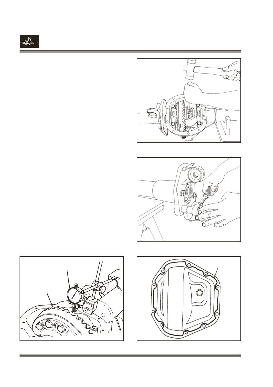
Check ring gear and pinion backlash in the three
equally spaced points with dial indicators.
Fig. 59
Backlash tolerance is 0.13 mm to 0.23 mm and should
not vary more than 0.08 mm between points checked.
High backlash is corrected by moving the ring gear
closer to the pinion. Low backlash is corrected by
moving the ring gear away from the pinion.
These corrections are made by switching shims from
one side of the differential case to the others.
Note :
If backlash is to specification, check the right
gear and pinion tooth contact pattern, and
adjust accordingly.
Refer to the Rear Axle section for details.
Install axle shafts through side gear spline. Place the
snap ring in the shaft's groove.
Fig. 60
Assemble Cylindrical roller bearing in carrier housing
using Dolley to pressing cylinder roller bearing in
housing Pt. no. 2704 5809 3306.
Assemble the oil seals using installer pinion oil seal
Pt. no. 2698 5890 3513 and handle universal Pt. no.
2698 5890 3506.
Install the mounting brackets, assemble the new
ones, if required and torque the four bolts (each
side) to 54-75 N.m.
Fig. 61
Note :
Brackets are not interchangable.
Apply sealent to cover plate surface.
Fig. 62
The bead must be 1/8 to 1/4 in high and wide.
Tighten the cover screw evenly to a torque of
38-45N.m.
Allow one hour curing time before vehicle operation.
Fill specified oil after curing.
Fig. 60
Fig. 61
Fig. 62
Fig. 59
CONTOUROF
BEAD
DIAL INDICATOR
WITHBRACKETRY
RINGGEAR