


 1481 / 1525

ELECTRICALS
91
SAFETY PRECAUTIONS :
Make sure to read the “Service /User Manual” for safety
precautions before opening / replacing / servicing the
system.
Please make sure the vehicle is well parked at a safe
place and the engine and the power of the vehicle
are switched off.
Avoid installation outdoors under a thunder/raining
situation.
INSTALLATION :
Follow these steps to install the Camera & Module Box
on to Bumper Assembly: (This is done before Bumper
is fixed to Vehicle & when Bumper reinforcement is
not yet mounted)
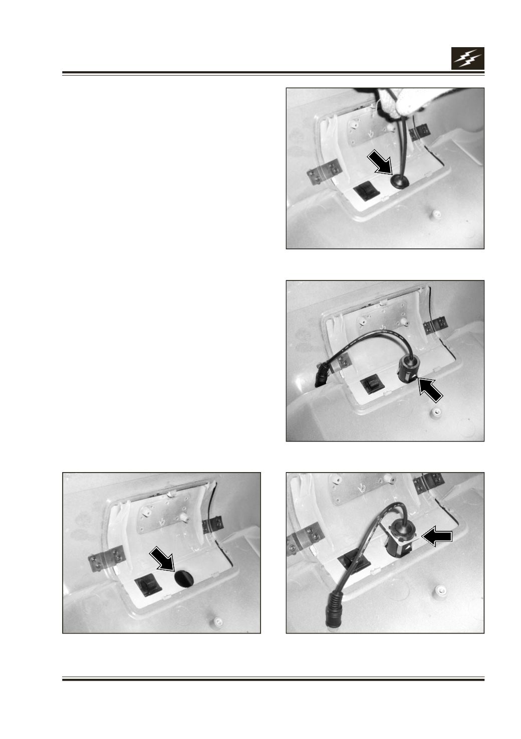
1. Insert (Camera) Cap-Ring /Base on to Camera
Housing until it clicks on to 4-Camera clips,
keeping broad side facing the same side as
Camera Lens.
2. Push Camera firmly thro’ 25 mm dia. hole provided
in the Tow Cover (Fig.2) from connector side
until it clicks on to 4-Camera clips.
Please turn the white mark on the camera to top
side. This will ensure that image on the Monitor
will be up-right & not inclined or up-side down.
(Fig.3)
3. Insert Metal Pad Lock on Camera Housing until it
touches inner side of Tow Cover & until it clicks on
to 4-Camera clips. (Fig.4)
Fig.1
Fig.2
Fig.3
Fig.4