


 1484 / 1525

ELECTRICALS
94
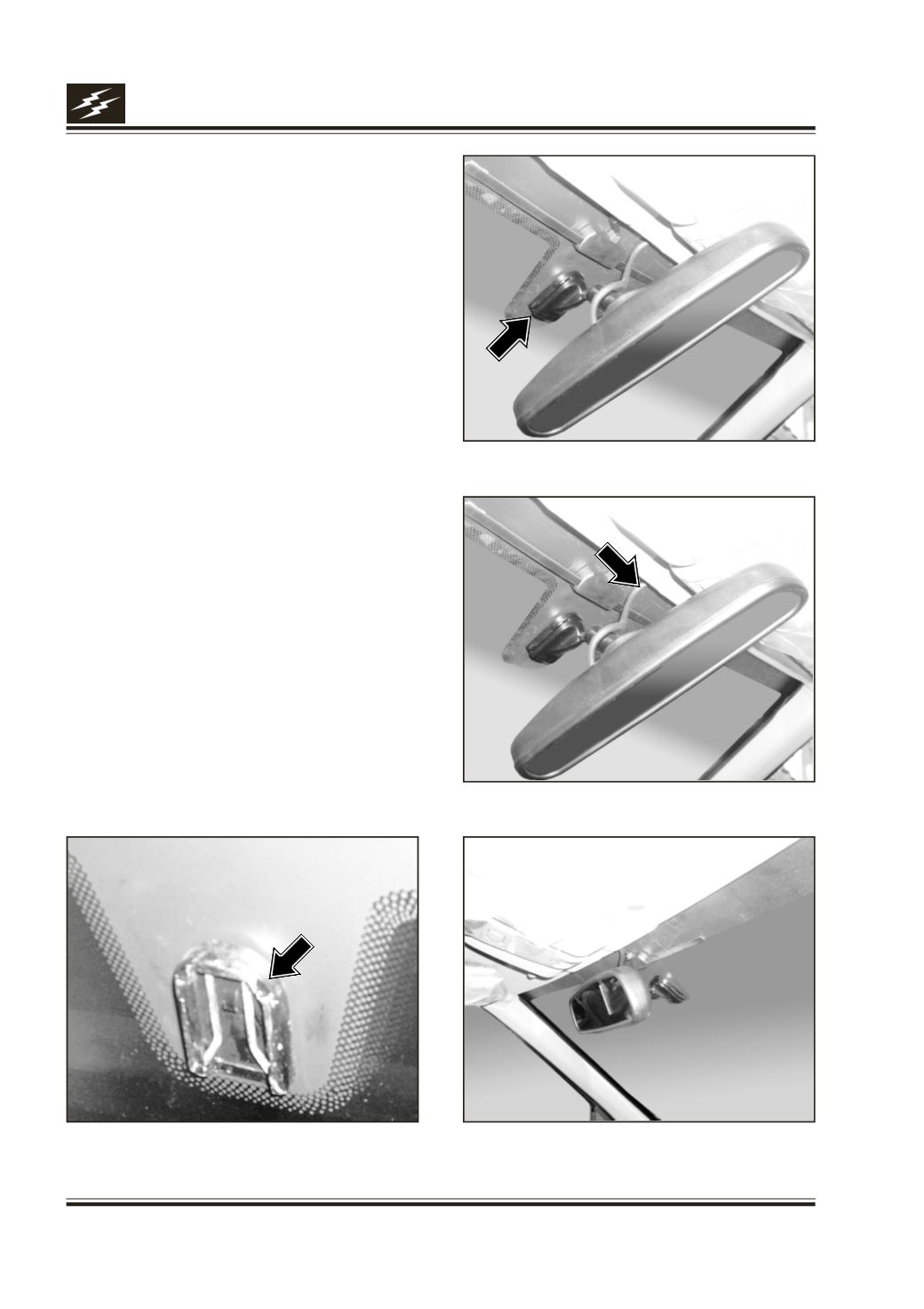
2. To turn MR-201 in 90 Deg. Clockwise. Please do
not turn only Mirror, but with Stem. To push Stem
of the mirror into Stem Mount firmly upwards
(Fig.13) & to turn the mirror to 90 Deg. Anti-
clockwise, until it locks in position into stemmount
(mirror button) on the windshield (Fig.12) to
normal viewing position (Fig.15)
3. Connect the 4- pin mini DIN of Mirror cum Monitor
to Mirror side wiring 4- pin mini DIN, properly
matching white arrows on both connectors. Cover
the joint by good insulation tape, to avoid water
entry. (Fig.14)
4. Connect the 2- pin Connector of Mirror cum
Monitor to 2-pin connector of power supply
interlocked with Reverse Gear Switch.
5. The Assembly should look like the photo below
(Fig.15)
For dismantling or replacement please follow the
reverse steps.
Precaution: If there is no image on LCD Monitor or
image is blurred or it is blank, while reversing, it
should be checked for all components are functional
& all connections are intact. Also to check for 12 V DC
Power reaching Camera & Mirror.
Fig.12
Fig.13
Fig.14
Fig.15