


 1229 / 1525

ENGINE
62
C-1
I J -
1
C-2
IJ-2
C-3
IJ-3
C-4
IJ-4
Fig A
Fig 2
Fig 3
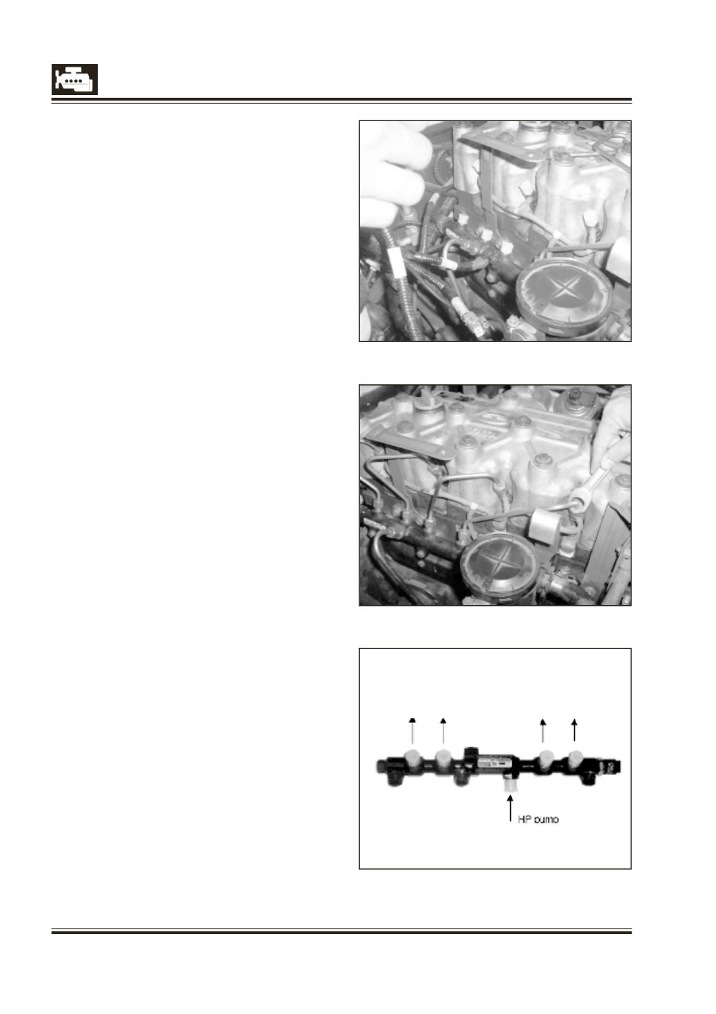
5 Remove the HP pipe. Vacuum any contaminants
from the inlet/outlet connections (rail and
injector). Protect inlet/outlet of the rail &
injector with the appropriate plugs from the
service kit.
(Fig: - A.)
HP pipe fitment procedure (Rail to Injectors)
Allocation of the outputs of the rail
(Fig: A)
Before fitment of HP pipes slacken the rail
mounting nuts in order to reduce the strain on the
pipes.
Following sequence to be ensured while fitting HP
pipes:
1. Remove the new pipe from its packing at the
last moment.
2. Remove the plugs and align the HP pipe from
pump to rail inlet. Remove corresponding rail &
injector protection plugs for the 1
st
cylinder.
3. Locate the injector end of the pipe in its cone
& hand tighten the nut.
4. Follow this procedure for 4
th
, 2
nd
and 3
rd
cylinder.
5. Then tighten the rail mounting bolts to the
specified torque.
6. Tighten the cap nuts to the specified torque of
HP pipe from rail to injector in the sequence of
1
st
, 4
th
, 2
nd
and 3
rd
cylinder. The order First rail
end and then injector end is critical.
7. If necessary reconnect and secure the PCV and
hoses.
8. Connect the battery.
9. Start the engine and allow the engine speed to
stabilize.
10. Check the HP connectors are sealed.
11. Erase the trouble codes caused by the
operations.
12. Stop engine.
13. Refit all components removed to aid
accessibility.