


 121 / 1525

82
4 DLT ENGINE
diaphragms within the boost controller. The boost
pressure is piped and connected to the chamber
formed between the two diaphragms. The diaphragms
sense the variation in the boost pressure and maintain
the balance between the fuel delivery and the boost
pressure, by continuously varying the pressure behind
the actuating pistons.
Operation :
At cranking speeds, the assembly is held in Excess
Fuel position (Full Boost) by a spring. As the engine
picks up, the transfer pressure builds up behind the
actuating pistons and moves the assembly to
minimum fuel position.
As the boost pressure increases with the rise in engine
speeds, the diaphragm responds and allows the
pressure to leak acting behind the actuating pistons.
This allows the return spring to move the assembly
axially towards increased fuel delivery position.
6. EGR THROTTLE SWITCH
The EGRThrottle Switch fitted on to the throttle lever
is used to sense the position of the throttle lever. The
output is given EGR controller.
7. COLD IDLE ADVANCE
The Solenoid operated Cold Idle advance is driven by
the glow plug timer (GPT) and overrides the normal
advance control mechanism when the engine is cold.
This normally functions in conjunction with the engine
Pre / Post heat system and operates only when the
electrical input is supplied to it by the GPT.
AIRVENTING
The DPC pumps are self venting pumps and therefore
allows the air entering into it, to go out through the
return line. However, it is recommended that whenever
the fuel lines are disconnected, the system is to be
primed in order to fill the system with fuel and remove
the air present in the system completely.
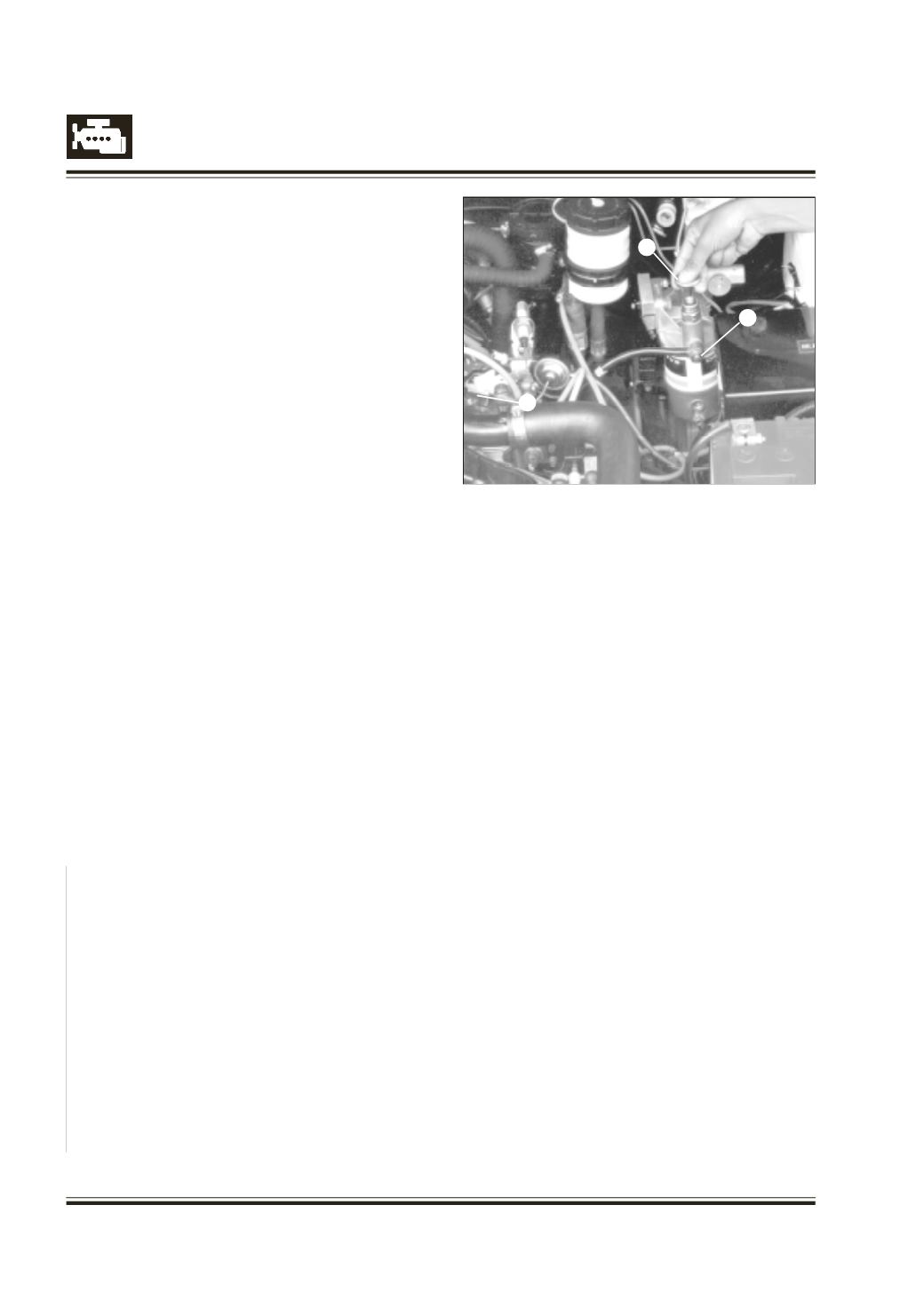
Procedure
l
Energise the Fuel Shut-Off Solenoid (Switch 'ON'
the ignition switch).
l
Loosen the following vent screws
On the banjo bolt at the filter outlet
À
On the FIP timing chimney plug
Á
(See fig. 166)
l
Loosen the priming pump plunger
Â
and actuate
the pump until clear fuel comes out of the vent
screw
À
l
Tighten the vent screw
À
l
Continue actuating the priming pump plunger until
clear fuel is seen coming out from the vent
screw
Á
l
Tighten the vent screw
Á
and then the priming
pump plunger
Â
Loosen one of the HP connections at the injector
end. Crank the engine for few seconds; and see
that the fuel flows out of the injector line.Tighten
the HP connection.
Start the engine and see that there is no fuel
leak from any of the points/connections.
Fig. 166
2
1
3