


 768 / 1588

29
BODY
9. REMOVAL/INSTALLATION OF DOOR LATCH
(Fig. 11 & 12)
REMOVAL
l
Remove the inner trim
l
Pull out required portion of plastic membrane.
l
Disconnect links and electrical connections from
door latch micro switch.
l
Remove 3 mounting screws, washers and latch.
l
Remove latch.
INSTALLATION
l
Locate latch on door.
l
Install 3 washers (C6.4), 3 sl. csk. screws
(M6x16) and tighten the screws.
l
Connect links properly.
l
Connect electrical connection of micro switch.
l
Ensure proper functioning of latch.
l
Apply sealant (Butyl mastic) on the door inner
panel and fix plastic membrane on it.
l
Fit the inner trim.
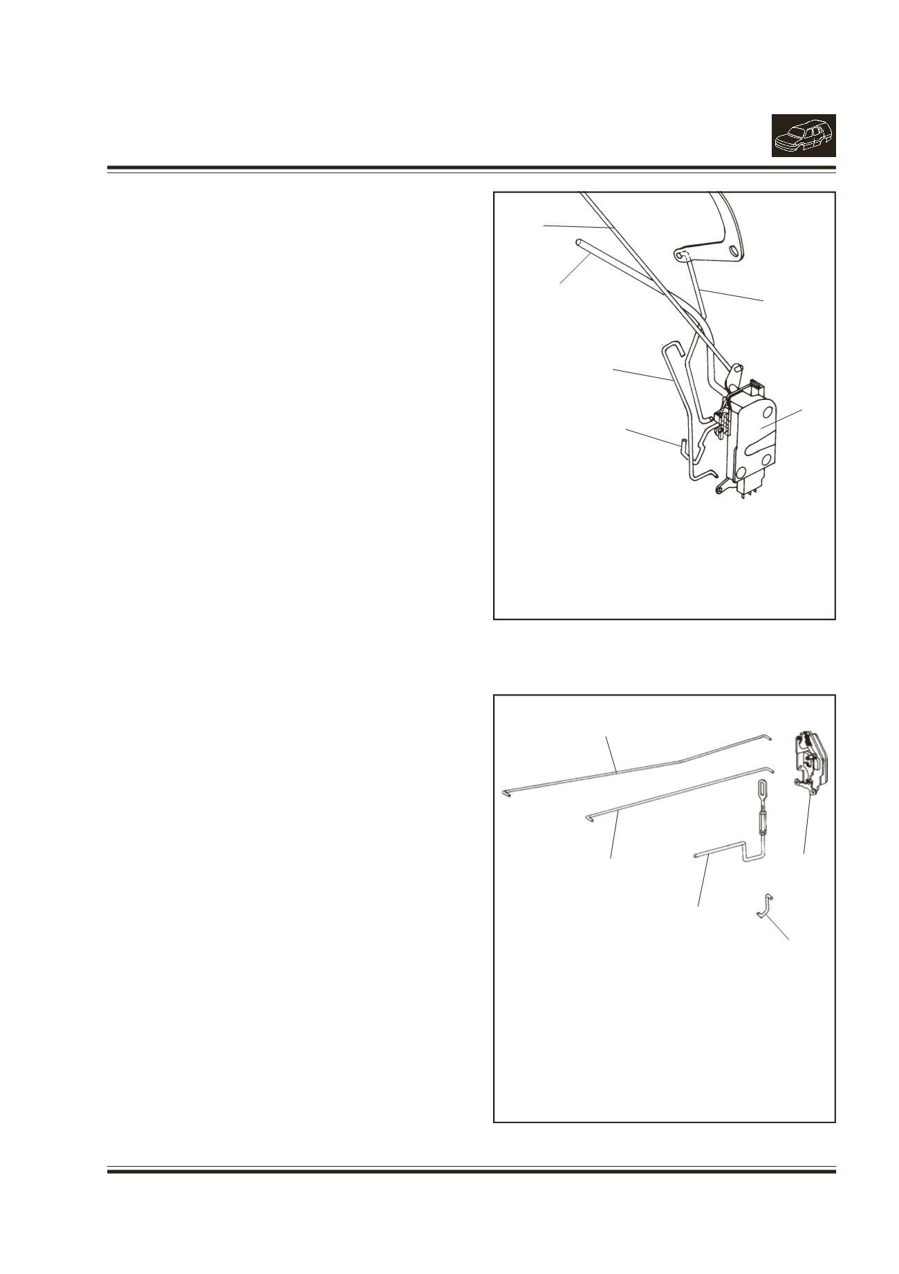
Fig. 11.
1.
LINK (BELL CRANKTO LATCH)
2.
LINK OUTER HANDLE
3.
LINK INNER HANDLE
4.
LINK SOLENOID
5.
LINK LOCK BARREL
6.
LATCH FRONT DOOR
2
1
3
4
5
6
Fig. 12.
1.
LINK LOCKINGKNOB
2.
LINK INNER HANDLE
3.
LINKOUTER HANDLE
4.
LINK SOLENOID
5.
LATCHREARDOOR
1
2
3
4
5