


 213 / 1588

68
486 PL ENGINE
P
Fig. 166
Fig. 165
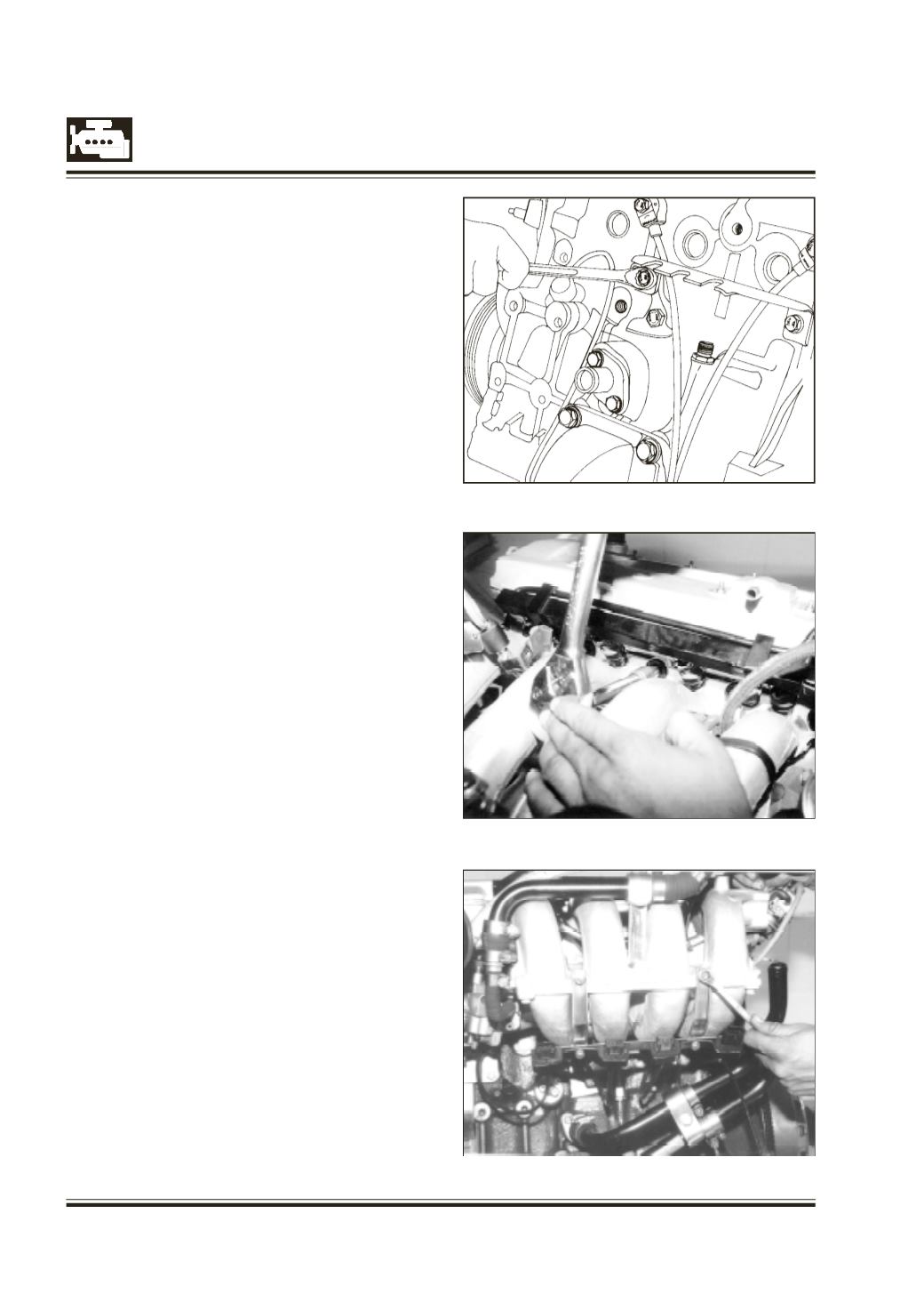
Install timing gear train cover.
Tighten cover mounting bolts.
Install inlet manifold bottom suppor t bracket.
Fig. 165
Fig. 167
Install the inlet manifold sub assy. on cylinder head
along with gasket. Fig. 166
Fit the bracket, which holds knock sensor pin
connector, speed sensor pin connector & phase
sensor pin connector, on intake manifold. Fig. 167