


 1113 / 1588

42
GEAR BOX G-76
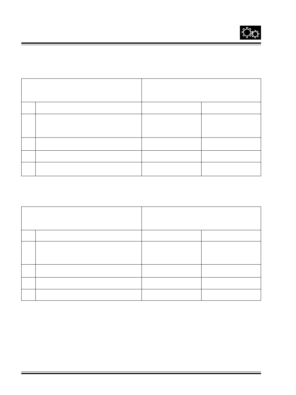
The control dimension to be maintained between
198 ± 0.1mm
Counter Shaft 3rd gear rear face and
housing face-Rear half.
1.0 Dimensions to be measured
Symbol
Example
1.1 Measure the dimension between Counter
A
200.00
Shaft 3rd gear rear face and taper roller
bearing outer race face. Fig. 90 and 92
1.2 Measure the rear cover depth. Fig. 90 and 92
B
2.30
1.3 DifferenceA-B
C
197.70
1.4 Shims required : 198 – C
D
0.30
19. MEASUREMENT OF CONTROL DIMENSIONS (FOR SELECTIONOF SHIMS)
OVER THECOUNTERSHAFT
OVER THE MAIN SHAFT
The control dimension to be maintained between
197±0.1mm
Main Shaft 2nd gear shoulder face front and
housing face - Rear half
2.0 Dimensions to be measured
Symbol
Example
2.1 Measure the dimension between Main Shaft
E
202.00
2nd gear shoulder face front and taper roller
bearing outer race face Fig. 91 and 93
2.2 Measure the rear cover depth Fig. 91 and 92
F
5.50
2.3 Difference E – F
G
196.50
2.4 Shims required 197 – G
H
0.50