


 1115 / 1588

44
GEAR BOX G-76
During measurement, remove compression spring. Check for the spacer of measured thickness, thrust bearing
and needle roller cage in drive shaft bore. Place drive shaft assembly over main shaft assembly.
OVER THE DRIVE SHAFT
The control dimension to be maintained between Drive Shaft synchro
11.1 ± 0.1 mm
ring front face to engaging gear 3rd/4th shoulder face
3.0 Dimensions to be measured.
Symbol
Example
3.1 Place Drive Shaft over Main Shaft Assy. with spacer of
I
4.50
measured thickness
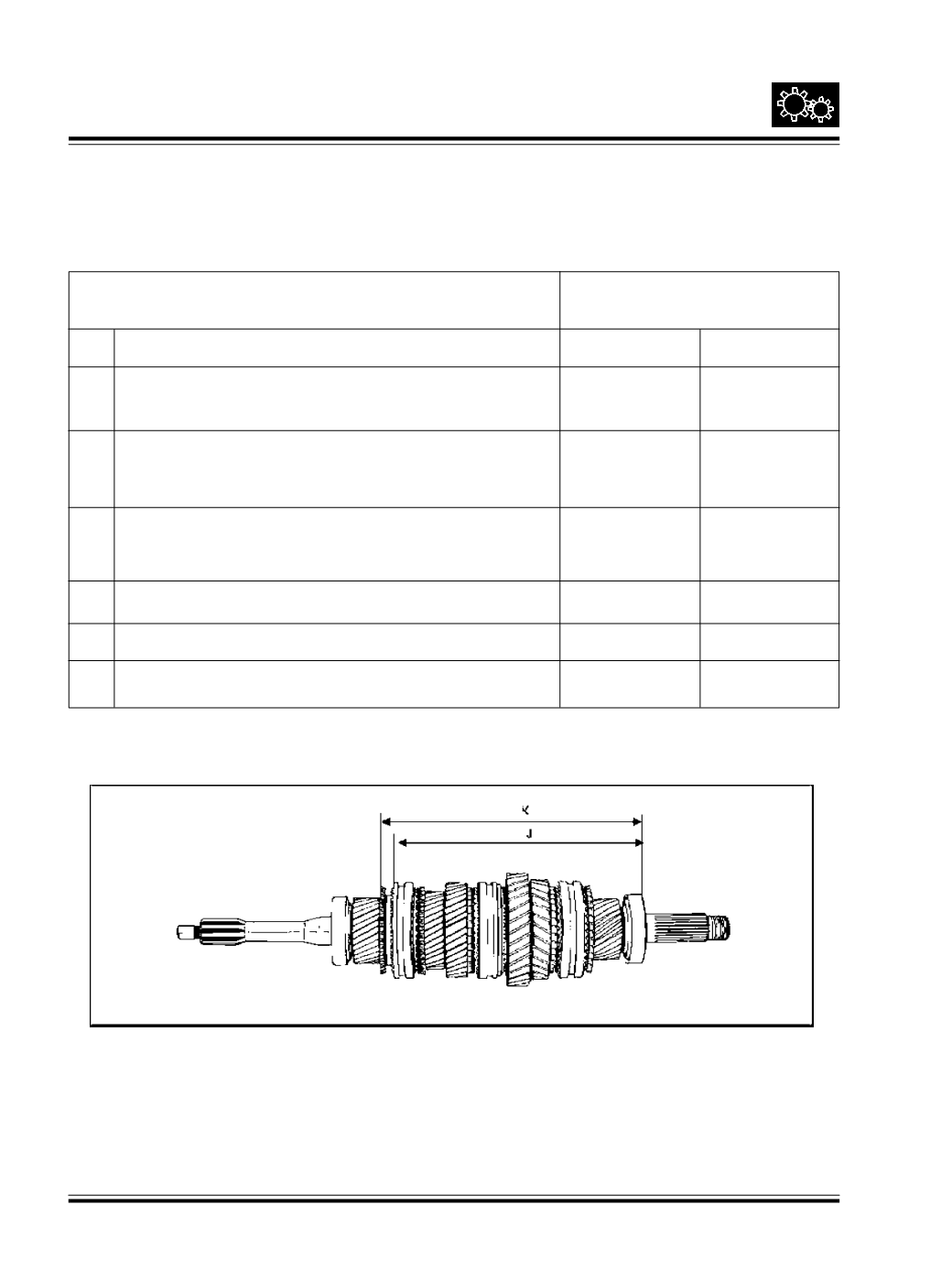
3.2 Measure the dimension between engaging gear 3rd/4th
J
252.00
shoulder face to Taper Roller bearing outer race face on
main shaft Fig.96 and 97
3.3 Measure the dimension between Drive Shaft synchro ring front
K
262.80
face to Taper Roller bearing outer race face on main shaft
Fig. 96 and 97
3.4 Difference K-J
L
10.80
3.5 Incremental spacer thickness required 11.1-10.8
M
0.50
3.6 Spacer thickness required 4.50 + M
N
5.00
Fig. 96