


 1108 / 1588

37
GEAR BOX G-76
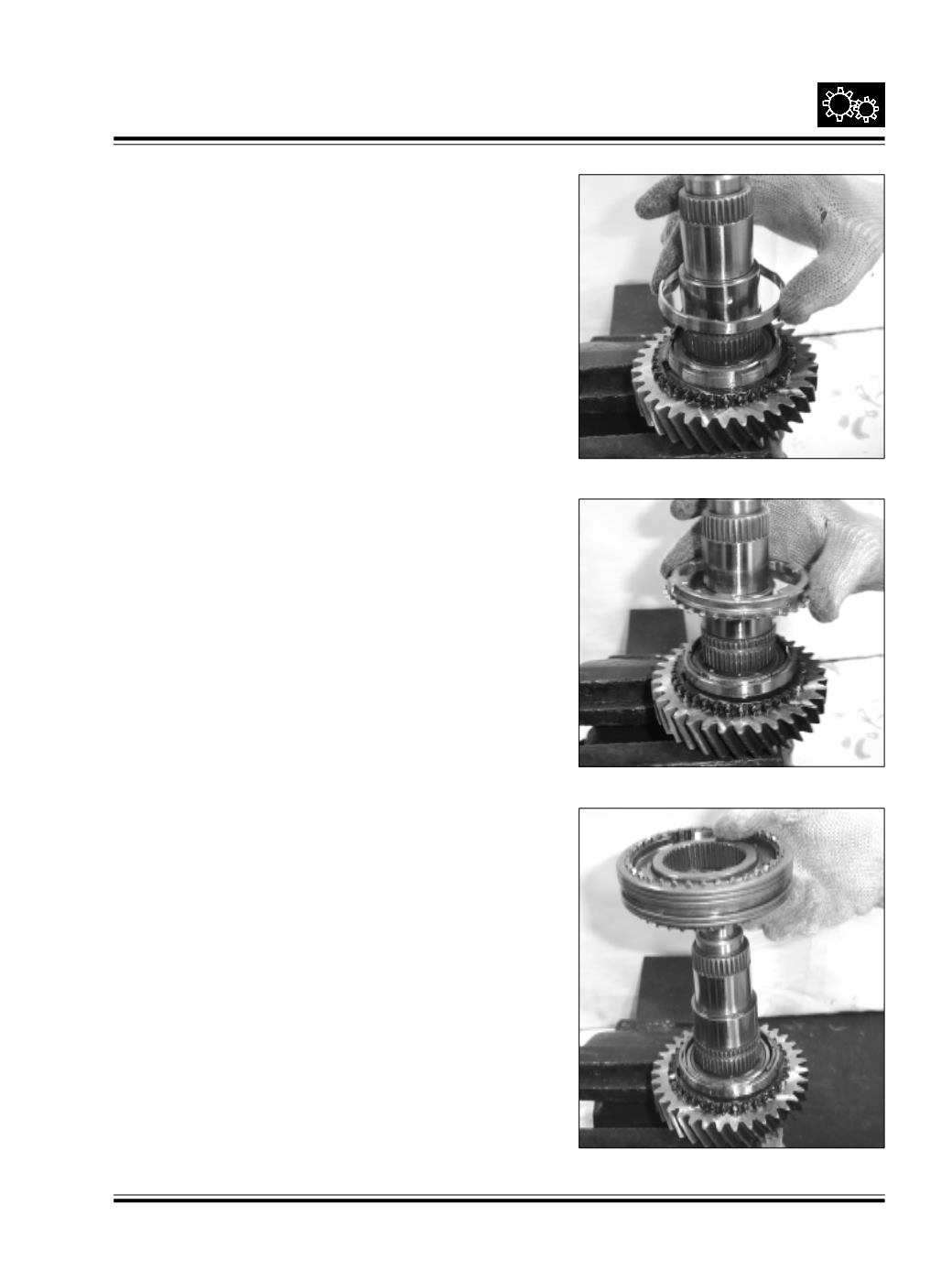
Place the intermediate synchro cone on the inner cone.
Ref Fig. 77
Fig. 77
Place the outer synchro cone on the intermediate cone.
Ref Fig. 78
Fig. 78
Insert the 1st / 2nd engaging gear assembly with shifter
sleeve, synchro springs, carrier and balls on the outer
synchro cone.
Ref Fig. 79
Fig. 79