


 765 / 1235

STEERING
36
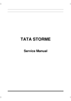
4. Disconnect the outer ball joint from the knuckle
by removing the split pin
(1)
and hexagonal thin
nut
(2).
Follow the same procedure at other end
also.
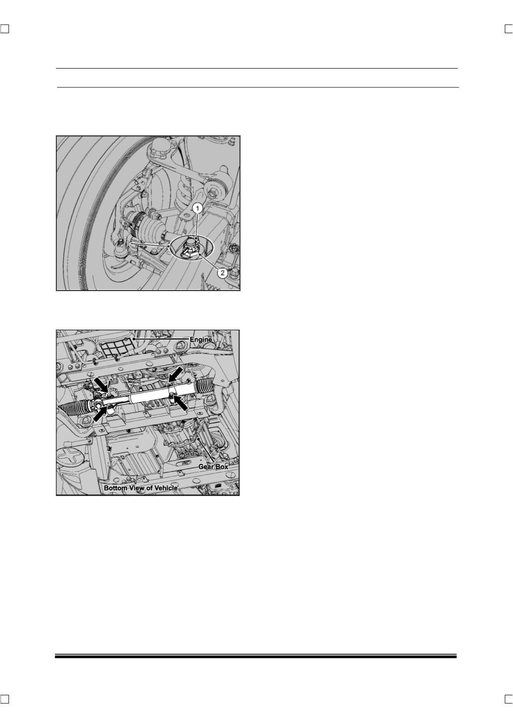
5. Loosen and remove four mounting bolts and
take out the rack and pinion assembly from the
frame.
FITMENT
For assembly follow reverse procedure of removal.
7.3 RACK & PINION UNIT OVERHAULING
7.3.1 General Instructions
The following general precautions to be followed
during servicing and during overhauling of rack and
pinion assembly;
•
Plug the ports tight with protective caps in the
steering gear.
•
Take care to avoid damages to bellows, feed
pipes, and input shaft while removing the RAP
assembly from the vehicle.
•
Do not attempt to weld any broken steering com-
ponent. Replace the component with the original
equipment.
NOTE
Due to the complexity of the power rack and pinion
unit, this portion of the manual only covers minor
repair of the power rack and pinion unit. Only proper-
ly trained and qualified technicians should perform
these repairs