


 1006 / 1235

ELECTRICAL
228
REFITMENT:
1.Fit the Audio supplementary unit by tightening
its two mounting screw.
Tightening torque for screw – 0.6 Kgm
2.Connect the electrical connection of audio
supplementary unit.
3.Fit the glove box assembly.
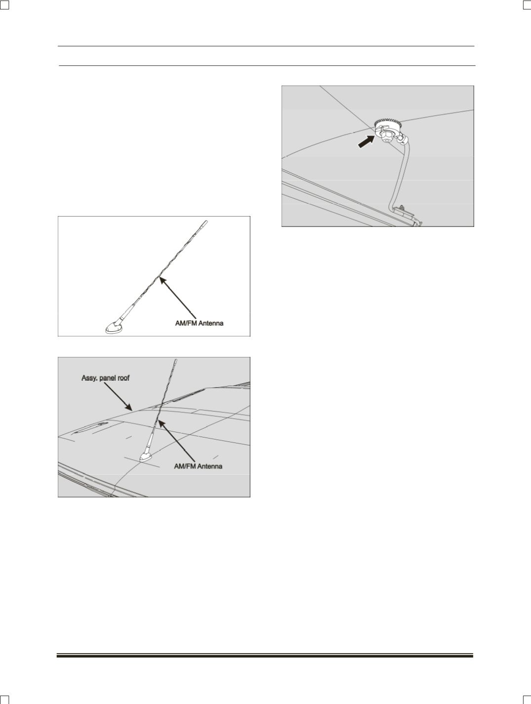
3. AM/FM ANTENNA:
The antenna is an electromagnetic circuit
component designed to effectively capture
radiated RF signals in the AM and FM bands.
LOCATION: It
is fitted on assembly panel roof.
REMOVAL:
1.Remove roof linear assembly (
Refer body
section
).
2.Remove one mounting screw of antenna.
3.Pry out the AM/FM antenna from top and
bottom.
REFITMENT:
1 Locate the antenna in the cutout provided on
assembly panel roof.
2. Fit the AM / FM antenna by tightening its one
mounting screw.
Tightening torque for screw – 0.6 Kgm
3. Fit the roof linear assembly.