


 115 / 1428

ENGINE 273 MPFI
109
ENGINE
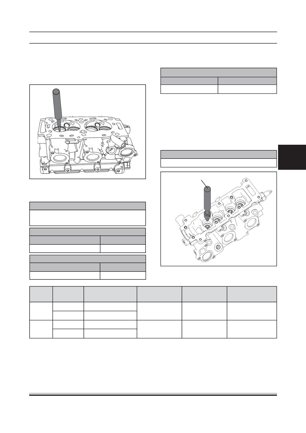
VALVE GUIDES:
•
In case of valve stem sticking in valve guide before
or excessive clearance between them, remove
valve guide alongwith valve guide seal fromcylinder
head using drift (Part No.2868 5890 06 05).
Size Valve type Valve guide bore Valve guide OD Valve guide ID Valve guide
in cyl. Head in mm in mm
in mm
Length in mm
Normal Inlet
11 H7
11.055 mm
5.5 ±0.05
33
Exhaust
11 H7
to 11.065 mm
Normal 1 Inlet
11.1 H7
11.155 mm
5.5 ±0.05
33
Exhaust
11.1 H7
to 11.165 mm
•
Using micrometer & bore gauge, take diameter
readings on valve stems & guides to determine
the stem clearance in the guide.
CAUTION
Be sure to take a reading at more than one place
along the length of each stem & guide.
VALVE STEM TO VALVE GUIDE CLEARANCE (INTAKE)
STANDARDVALUE
WEAR LIMIT
0.025 to 0.051 mm
0.07 mm
VALVE STEM TO VALVE GUIDE CLEARANCE (EXHAUST)
STANDARDVALUE
WEAR LIMIT
0.057 to 0.083 mm
0.09 mm
•
Check valve guide bore diameter in cylinder head
and if necessary, ream valve guide bore in cylinder
head to next over size.
VALVE GUIDE BORE DIAMETER IN CYLINDER HEAD
STANDARDVALUE OVERSIZEAVAILABLE
11 mm H7
11.1 mm H7
•
Install matching size valve guide in cylinder head
using drift (Part No.2868 5890 06 05) and spacer
(Part No.2834 5890 06 02)
•
Ream valve guide inside diameter. It should be
within specified limit .
•
Fit valve guide oil seals using drift (Part No.2868
5890 06 05) and spacer (Part No. 2834 5890 06
04).
VALVEGUIDE INSIDE DIAMETER
6 mm H7
2868 5890 06 05