


 602 / 1980

590
STEERING SYSTEM
1146 mm
LH/RH variation in castor
45'
Rear wheel alignment data (Unladen condition)
Camber angle
0.75° (+ve)
Toe-Out
9’
NOTE :
(a) Please follow manufacturer’s (of tire replacement
machine) manual for wheel alignment instructions,
recommendations and any other additional
information.
(b) All adjustments for wheel alignment are to be done
in UNLADENCONDITIONONLY.
(c) Only TOE IN value has to be adjusted while doing
wheel alignment. Rest of the values remains fixed
i.e. NOadjustments are required. Refer above table
for standard values.
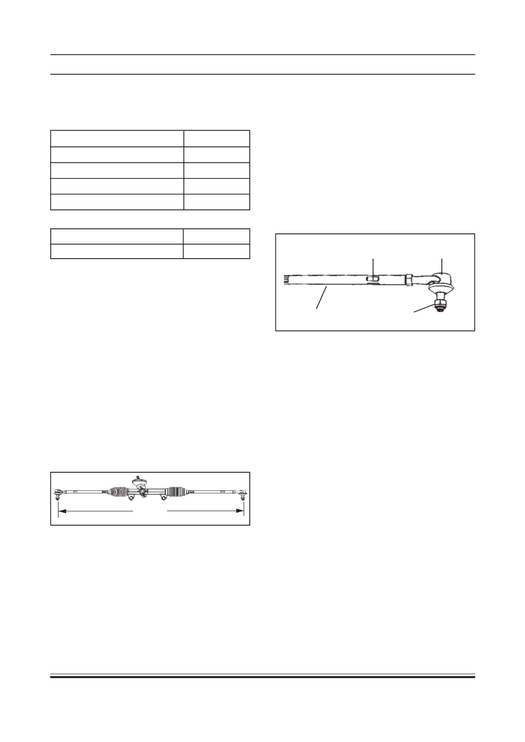
1. Steering rack & pinion gear comes with 1146 mm
(nominal) length between centers of the ball
joints with tie rods parallel to the rack. (As
shown in following figure) Ensure that number of
threads of outer ball joints exposed out of the tie
rod tube is same on LH and RH side
2. Mount the steering rack & pinion gear at its
mounting location. Assemble the steering column
with steering wheel. Do not tighten the steering
wheel to full torque.
3. Rotate the steering wheel from lock to lock.
Measure the number of turns.
4. Bring the steering gear to centre by rotating through
half the number of measured turns.
5. Remove the steering wheel & refit it so that spokes
& mascot (T-emblem) are correctly positioned.
6. Ensure that both front tires are in straight ahead
position. Tighten the steering wheel nut to specified
torque.
7. Fix the outer ball joints into the steering arm of
suspension and rotate the steering wheel to bring
the spokes to the correct position.
8. Adjust toe-in as given below.
(a) Toe-in is adjusted by varying the length of tie rods
after loosening their lock nuts (as shown in above
figure). After adjusting the length of tie rods
recheck toe-in and tighten back the lock nuts.
Increasing length of tie rod will reduce the toe-in
and vice-versa.
(b) While adjusting toe-in, adjust the length of both tie
rods by rotating them in the same direction such
that their lengths remain equal at all times.
NOTE :
Toe - in is the difference in distance between the front
of the wheels and the rear of the wheels
.
9. Check the position of theT-emblemand the spokes.
If the steering wheel is not centered, adjust the
tie rod lengths by reducing one and increasing the
other so that in the SAP (Straight Ahead Parked)
condition the toe is correct and yet steering wheel
is centered.
Tie rod end
Adjuster
Nyloc Nut
Tie rod
Procedure for steering geometry adjustment
(wheel alignment) on vehicle:
Front wheel alignment data (Unladen condition)
Camber angle
1.0° (+ve)
Castor angle
7.4°
Toe-in (SUM)
12 mm
Wheel lock angle (Outer)
37°