


 1080 / 1980

TRANSAXLE
136
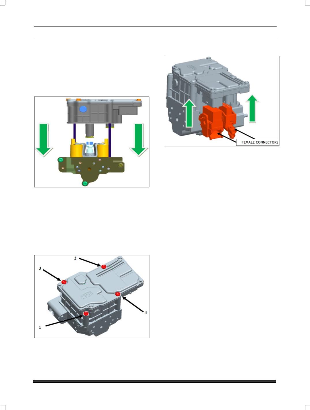
3. Position the ‘Transmission Control Unit’ over
the electro valve block, still using for reference
the two ‘Special tool – guide rods’ and moving
it parallel towards the mating surface.
Insertion of all the electro valves, pressure
sensor and ground tabs must be obtained by
appropriate load on the ‘Transmission Control
Unit’ heat sink and following handling
precautions.
4. Once the ‘Transmission Control Unit’ is
positioned mated to the electro valve block,
remove the two ‘Special tool – guide rods’.
5. Insert the new
four ‘Transmission Control Unit’
fixing screws into the corresponding holes
and tighten each screw by applying a torque
of 6.0 ± 1.2 Nm, following the order shown in
the image below. Please consider that screw
on pos. 1 is M5 x 55and screws on pos. 2, 3
and 4 are M5 x 68.
6. Engage the two female connectors with the
cable on the ‘Transmission Control Unit’.