


 829 / 1904

776
BODY
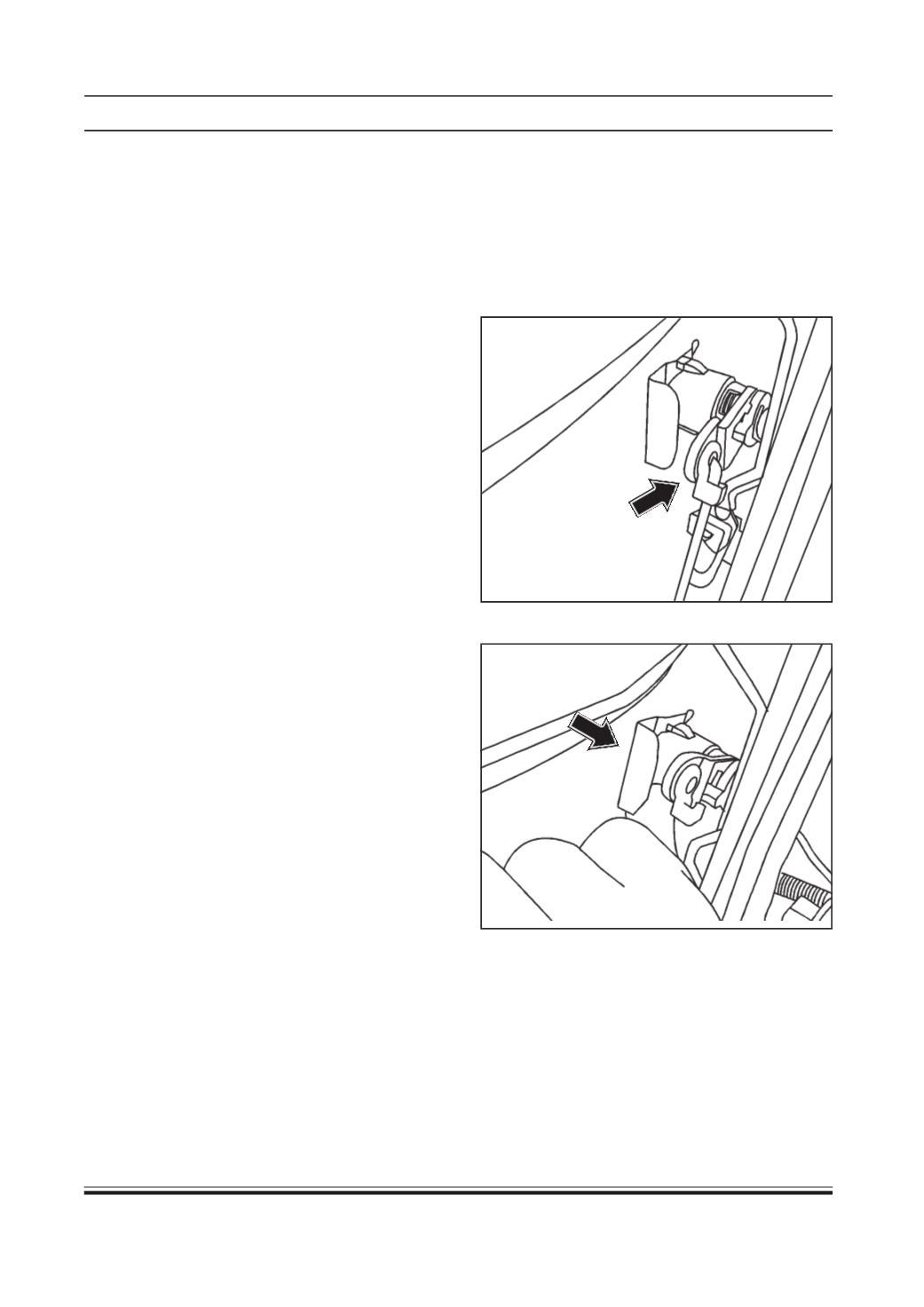
4. Remove the locking clip of lock barrel.
Inspection
1. Inspect central locking master cum follower unit.
(Refer Body Electrical Group)
2. Inspect latch assembly for any damage or any
bend linkages.
Installation
1. For vehicle with central locking unit.
(a) Assemble central locking master cum follower unit
with latch assembly by tightening mounting
screws.
(b) Connect the electrical connector of central locking
master cum follower unit.
2. Tighten three screws of latch assembly to specified
torque.
TIGHTENING TORQUE FOR LATCH SCREWS = 1 Kg-m
3. Engage following links :
(a) Door inner handle link – from door inner handle to
latch assembly.
(b) Outer handle link – from outer handle to latch
assembly.
(c) Door lock barrel link – from door lock barrel to
latch assembly. (For vehicle with central locking
unit)
4. Tighten the bolt of guide channel.
5. Fit door pad. (Refer front door pad installation
procedure)
NOTE :
On front passenger door, latch assembly is
assembled with central locking follower unit whose
removal and installation procedure is similar to that
of driver’s side.
FRONT DOOR LOCK BARREL
Removal
1. Lift the glass to upper most position.
2. Remove door pad. (Refer front door pad removal
procedure)
3. Disengage the link from the lock barrel.