


 591 / 1904

STEERING SYSTEM
579
STEERING
6. Follow steps (4) and (5) to remove tie rod ball joint
from other side.
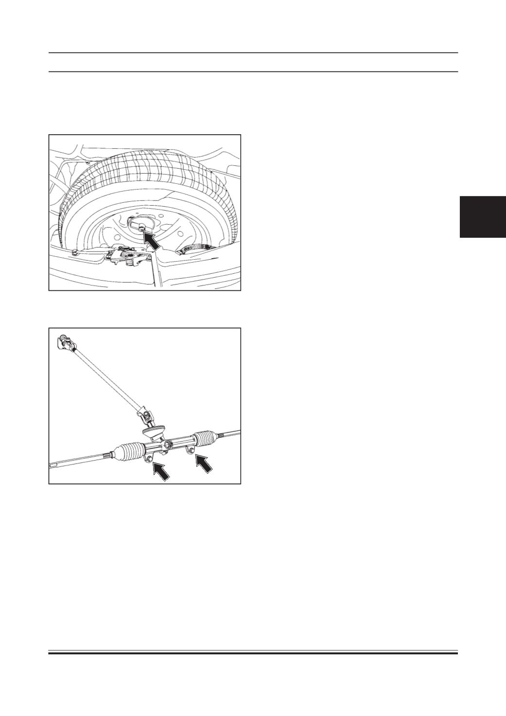
7. Unscrew spare wheel knob and remove spare
wheel
8. Remove two mounting bolts of steering rack and
pinion assembly
9. Take out steering rack and pinion assembly from
either side of steering knuckle.
Inspection
1. Remove rubber seal from the steering rack and
pinion assembly and inspect the condition of
rubber seal i.e. for any cut or damage. Replace
rubber seal if found damaged.
2. Inspect steering rack for any external damage.
Replace damaged or worn out parts.
3. Check condition of tie rod ball joint. If found cracked
or excessive play, replace ball joint.
4. Replace tie rod ball joint nyloc nut.
5. Check free rotating torque of pinion shaft. If found
jammed, replace steering rack assembly.
6. Inspect rubber bellows for any rupture.
Installation of steering rack and pinion assembly
on vehicle :
1. Fit rubber seal on steering rack assembly.
NOTE:
Please ensure the correct fitment of rubber seal on
steering rack assembly.
2. Insert steering rack and pinion tie rod ends through
either side of steering knuckle.
3. Tighten two mounting bolts of steering rack to
specified torque.
TIGHTENINGTORQUEFORMOUNTINGBOLTS
OF STEERING RACK AND PINION = 4.9 ± 0.2
Kg-m
4. Tighten both tie rod ball joint nyloc nut to speci-
fied torque.
TIGHTENING TORQUE FOR NYLOC NUT OF
TIE ROD BALL JOINT= 8.6 ± 0.2 KG-M
5. Tighten upper universal joint bolt to specified
torque.
TIGHTENING TORQUE FOR UPPER UNIVER-
SAL JOINT BOLT = 2.3 ± 0.1 Kg-m
6. Tighten lower universal joint bolt to specified
torque. (Thus securing steering column with rack)
TIGHTENING TORQUE FOR LOWER UNIVER-
SAL JOINT BOLT = 2.3 ± 0.1 Kg-m
7. Mount spare wheel and tighten the knob.
8. Check for toe settings and do wheel alignment if
required. Refer wheel alignment procedure)
9. Refit both front wheels.