


 588 / 1904

576
STEERING SYSTEM
Installation :
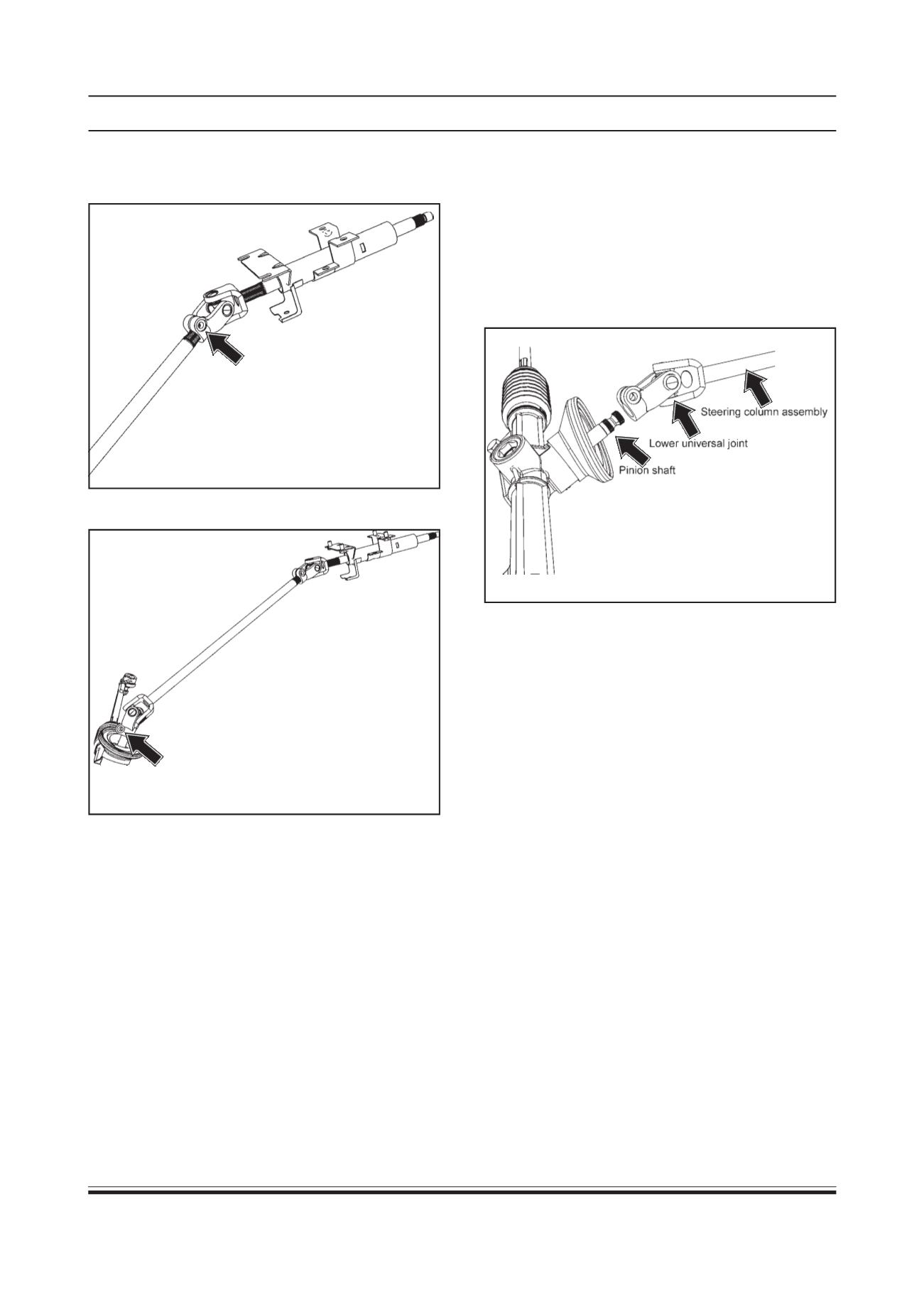
1. Align pinion shaft of RPS assembly with the lower
universal joint as shown in figure. Insert steering
column assembly into pinion shaft and then tighten
the bolt to specified torque.
TIGHTENINGTORQUE FORTHEBOLT SECURING
STEERING COLUMN ASSEMBLY TO THE
STEERING RACK = 2.3 ± 0.1 Kg-m
8. Remove lower universal joint bolt.
9. Remove steering column assembly with a gentle
tap (with mallet) on the lower universal joint.
Inspection :
1. Check steering column assembly for the following:
(a) Free rotation of steering spindle
(b) Steering spindle bottom for grease.
WARNING :
Do not disassemble the steering column assembly
in to column and shaft. If steering column or steering
shaft is found defective, replace as a complete
assembly.
7. Loosen upper universal joint bolt. (Do not remove
the bolt)
2. Tighten upper universal joint bolt to specified
torque.
TIGHTENING TORQUE FOR UPPER UNIVERSAL JOINT
BOLT = 2.3 ± 0.1 Kg-m
3. Tighten four nuts of steering column assembly to
specified torque.
TIGHTENING TORQUE FOR STEERING COLUMN
MOUNTING BRACKET BOLTS = 2.0 ± 0.1 Kg-m
4. Fit two screws of nacelle bottom cover.
5. Fit ignition switch and combi switch assembly.
(Refer ignition switch and combi switch assembly
installation procedure / Body Electrical group)
NOTE :
Ensure that side levers are fitted in their respective
place and correct connectors are connected.
7. Tighten mounting screws of both nacelle covers
(Upper and Lower)
CAUTION :
When tightening upper nacelle cover, ensure that
combination switch wires are not caught between the
covers.
8. Install steering wheel. (Refer steering wheel
installation procedure) and connect battery.