


 420 / 1904

414
DRIVETRAIN
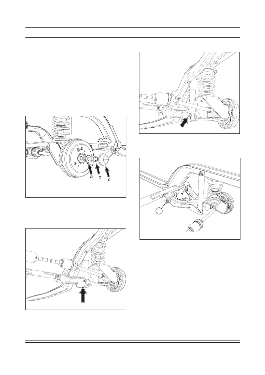
4. Support the semi trailing arm so that :
(a) It will prevent the semi trailing arm from flying
downward when the shock absorber is unbolted.
(b) Drive shaft angles are not exceeded.
5. Remove the lower mounting bolt of shock absorber.
6. Remove inner mounting bolt (1) and loosen outer
mounting bolt (2) from the cradle of semi trailing
arm assembly (Do not remove the outer bolt).
REMOVAL FROMVEHICLE
Removal
1. Drain transaxle oil (Refer transaxle oil drain
procedure/Transaxle group)
2. Remove wheel. (Refer wheel removal procedure/
Wheels and Tyres group)
NOTE :
Please ensure that parking brakes are applied.
3. Remove wheel hub cover (c), wheel lock nut (b)
and thrust washer (a)
1
2