


 952 / 1575

ELECTRICAL
132
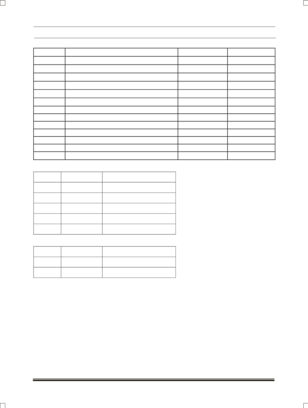
X1. J3
NC
Al
X1. J4
Bonnet Switch
DI
Low
X1. K1
Diagnostic K Line
X1. K2
Front Wiper Parking Switch
DI
Low
X1. K3
Rear Wash Switch
DI
Low
X1. K4
NC
DO
High
X1. L1
Ground
X1. L2
V Batt
X1. L3
V Batt
X1.L4
Roof Lamp
PWM
High
X1. M1
Left Indicator Lamps
PWM
High
X1. M2
Right Indicator Lamps
PWM
High
X1. M3
Mirror Unfold Relay
PWM
High
X1. M4
Mirror Fold Relay
PWM
High
BCM SIGNAL DESCRIPTION:
SR NO.
SIGNAL TYPE
SIGNAL DESCRIPTION
1
DI
Digital input
2
DO
Digital output
3
AI
Analog input
4
PI
Pulse input
5
PWM
Pulse width modulated
RF SIGNAL INPUTS ARE FOR:
SR NO.
SIGNAL TYPE
DESCRIPTION
1
RF
Approach lights
2
RF
Remote lock and unlock