


 947 / 1575

ELECTRICAL
127
ELECTRICAL
8.12 BODY CONTROL MODULE (
BCM
)
DESCRIPTION:
The body control module is the primary
hub that maintains functions, such as internal and
external lighting, security and access control,
comfort features for doors, and other convenience
controls
.
The BCM also acts as a terminating
resistor for EMS – IMMO CAN Network.
FEATURES OF BCM
Limp Home Mode
Monitors BCM Microcontroller Health through
in built Failsafe circuitry.
Without ignition ON turn on the .Left / Right
Indicators (
non-flash mod
e), parking lamp,
Head lamp and rear fog lamp.
BCM Power mode
The BCM will support the following power
modes internally.
BATTERY
RUN
In BATTERY mode, the required circuits
are active to allow functionality when the vehicle
engine is not running. Current consumption should
be less than 6mA. Diagnostics is not active in
BATTERY mode.
In RUN mode, all circuits are active and full
functionality is available.
Stuck Switch Monitoring
The Stuck Switch monitoring of certain
momentary switch inputs is used to detect when a
momentary switch is in the activated position for a
period longer than a predefined timeout and
maybe “stuck.”
A DTC shall be set when a stuck switch is
detected. The switch input is then ignored for the
rest of that ignition cycle or until the switch is
operated correctly. Following switches are
monitored for switch stuck functionality (
60 sec’s
timeout period)
,
Hazard Switch
Front wash switch
Rear wash switch
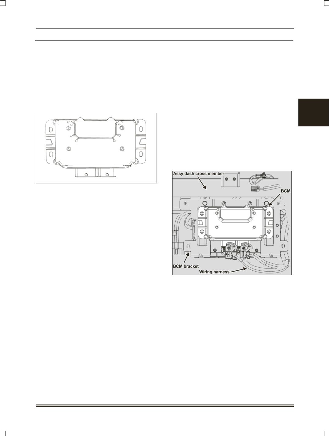
LOCATION:
It is located on BCM mtg bkt on assy
dash cross member.